
ROB-440 · Lesson 5 of 12 · 29 min
PLCs and IEC 61131-3 programming
In almost every robot cell, the robot is not in charge. A programmable logic controller (PLC) coordinates the cell: it reads sensors on conveyors and fixtures, tells machines and robots what to do and when, monitors guards through a safety controller, and talks to the operator panel and the plant's higher-level systems. Robot programmers who cannot read PLC code struggle to commission cells, and PLC programmers who do not understand robots write handshakes that deadlock. This lesson explains how PLCs work, introduces the IEC 61131-3 programming languages with short examples, and shows how a PLC and a robot exchange signals reliably. ROB-320 covered real-time systems in general; a PLC is a particular, very successful answer to the real-time problem for factory logic.
What a PLC is
The PLC was invented in 1968 and 1969 to replace the banks of relays that controlled automotive production lines. Changing relay logic meant rewiring cabinets; changing a PLC program meant editing software. The first programming language deliberately imitated relay wiring diagrams so that electricians could use it, which is why ladder logic still looks like a drawing of relay contacts and coils. Modern PLCs range from small units with a dozen inputs and outputs to large modular systems with thousands of points, redundant processors and integrated motion control. Major suppliers include Siemens, Rockwell Automation (Allen-Bradley), Schneider Electric, Mitsubishi Electric, Omron and Beckhoff, the last of which runs PLC software on industrial PCs.
PLCs are built for the factory: they tolerate electrical noise, vibration and temperature extremes; they run deterministic programs for years without rebooting; their input and output modules connect directly to 24 V DC sensors, solenoid valves, contactors and 4 to 20 mA analog instruments; and their programs can be monitored and modified while running. These properties, not raw computing power, are why PLCs remain dominant even though a laptop processor is far faster.
The scan cycle
A PLC executes its program in a repeating scan. At the start of each scan it reads all inputs into an input image table in memory. It then executes the user program from top to bottom using those stored values, writing results to an output image table. Finally it writes the output image to the physical outputs, performs communication and diagnostics, and starts again. Typical scan times are a few milliseconds to tens of milliseconds, depending on program size and processor.
Because inputs are read once per scan, the worst-case response time from an input change to an output change is about two scan times plus the input filter delay and the output switching delay. An input that changes just after it was read waits almost a full scan to be read, then a full scan to be processed and written. Short pulses can be missed entirely if they are shorter than one scan, which is why fast signals use interrupt inputs or high-speed counter modules.
Worked problem
Will the PLC catch the pulse, and how fast does it respond?
A PLC has a 10 ms scan time, a 3 ms input filter and relay outputs with a 10 ms switching time. A part-present sensor on a fast conveyor produces 8 ms pulses. A reject solenoid must fire within 40 ms of a fault signal. Is the configuration adequate?
Show solution
- The 8 ms pulse is shorter than the 10 ms scan, so the PLC may miss it entirely; a high-speed counter or interrupt input is needed, or a longer pulse.
- Worst-case response for the reject: \( 3 + 2 \times 10 + 10 = 33 \) ms.
- 33 ms is under 40 ms, but with little margin; a transistor output switching in under 1 ms would bring the worst case to about 24 ms.
Answer: The pulse can be missed; use a fast input. The reject path meets 40 ms with relay outputs but is better with transistor outputs.
Inputs and outputs
Discrete inputs and outputs in North American and European factories are mostly 24 V DC. Sensors are either sourcing, called PNP, which switch the positive supply to the input, or sinking, called NPN, which switch the input to 0 V. The input module must match: a sinking input module expects a sourcing sensor, and vice versa. Mixing them up is one of the most common commissioning errors. Analog signals are usually 4 to 20 mA current loops, chosen because current is unaffected by wire resistance and because a reading of 0 mA reveals a broken wire, or 0 to 10 V for short runs. Increasingly, sensors and valve terminals connect through IO-Link or a fieldbus rather than individual wires, which Lesson 6 covers.
Worked problem
Scaling a 4 to 20 mA signal
A vacuum transmitter on a robot gripper outputs 4 mA at 0 kPa vacuum and 20 mA at 100 kPa vacuum. The PLC analog input converts 4 to 20 mA into raw counts from 0 to 27,648, a common convention on some PLC families. A reading of 15,200 counts arrives. What is the vacuum, and what current is that?
Show solution
- Fraction of span: \( 15\,200 / 27\,648 \approx 0.550 \).
- Vacuum: \( 0.550 \times 100 = 55.0 \) kPa.
- Current: \( 4 + 0.550 \times 16 \approx 12.8 \) mA.
- A reading corresponding to below about 3.6 mA would indicate a wiring fault rather than zero vacuum.
Answer: About 55 kPa vacuum, at roughly 12.8 mA.
IEC 61131-3 languages
IEC 61131-3 is the international standard for PLC programming languages. Its fourth edition, published in 2025, keeps four languages: two graphical, Ladder Diagram (LD) and Function Block Diagram (FBD), one textual, Structured Text (ST), and Sequential Function Chart (SFC) for organizing sequences. A fifth, the assembly-like Instruction List (IL), was deprecated in the third edition of 2013 and removed in the fourth. The standard also defines program organization units (programs, function blocks and functions), data types, and standard timers and counters. Vendors implement it with their own extensions, so programs are not fully portable between brands, but the concepts are shared, and the PLCopen organization publishes common function blocks for motion control and safety.
| Language | Style | Strengths | Typical use |
|---|---|---|---|
| Ladder Diagram (LD) | Graphical, relay-like rungs | Easy for electricians to troubleshoot online | Discrete interlocks, simple machines, North American plants |
| Function Block Diagram (FBD) | Graphical, blocks wired together | Clear signal flow, good for analog and control | Process control, safety programs |
| Structured Text (ST) | Textual, Pascal-like | Calculations, loops, data handling, state machines | Complex logic, recipes, communications |
| Sequential Function Chart (SFC) | Graphical steps and transitions | Visualizes sequences and parallel branches | Machine sequences, batch processes |
A ladder rung reads left to right: contacts in series form a logical AND, contacts in parallel form an OR, and a coil on the right is energized when a path of true contacts connects the left rail to it. The classic start-stop circuit uses a seal-in, or latching, contact so that a momentary start button keeps a motor running until stop is pressed.
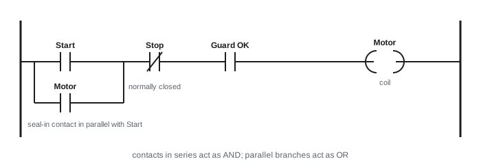
(* Same start-stop logic in Structured Text *)
ConveyorRun := (StartPB OR ConveyorRun) AND NOT StopPB AND GuardOK;

(* A TON on-delay timer: alarm if the part sensor stays blocked for 5 s *)
JamTimer(IN := PartSensor AND ConveyorRun, PT := T#5S);
JamAlarm := JamTimer.Q;

(* A CTU up-counter: count parts placed and flag a full pallet at 40 *)
PalletCount(CU := PartPlacedPulse, RESET := PalletRemoved, PV := 40);
PalletFull := PalletCount.Q;
Timers and counters are standard function blocks. TON, the on-delay timer, sets its output after its input has been true for a preset time; TOF, the off-delay timer, keeps its output on for a preset time after the input goes false; TP produces a fixed pulse. CTU and CTD count up and down. Edge detection blocks, R_TRIG and F_TRIG, produce a one-scan pulse when a signal rises or falls, which is essential for counting events rather than scans.
# Simulating the seal-in rung and a rising-edge counter over a few scans
scans = [  # (StartPB, StopPB, GuardOK, PartSensor)
    (0, 0, 1, 0), (1, 0, 1, 0), (0, 0, 1, 1), (0, 0, 1, 1), (0, 0, 1, 0),
    (0, 0, 1, 1), (0, 0, 0, 1), (0, 0, 1, 0), (1, 0, 1, 0), (0, 1, 1, 0)]
run, prev_part, count = False, 0, 0
for i, (start, stop, guard, part) in enumerate(scans):
    run = (start or run) and not stop and guard          # seal-in rung
    rising = part and not prev_part                       # R_TRIG
    if rising and run:
        count += 1
    prev_part = part
print(f"scan {i}: run={int(run)} part={part} rising={int(rising)} count={count}")scan 0: run=0 part=0 rising=0 count=0 scan 1: run=1 part=0 rising=0 count=0 scan 2: run=1 part=1 rising=1 count=1 scan 3: run=1 part=1 rising=0 count=1 scan 4: run=1 part=0 rising=0 count=1 scan 5: run=1 part=1 rising=1 count=2 scan 6: run=0 part=1 rising=0 count=2 scan 7: run=0 part=0 rising=0 count=2 scan 8: run=1 part=0 rising=0 count=2 scan 9: run=0 part=0 rising=0 count=2
Sequences and state machines
Robot cells are sequential: wait for a part, clamp it, tell the robot to load the machine, start the cycle, and so on. Sequences written as scattered ladder rungs become hard to follow and easy to break. Better practice is an explicit state machine, in SFC or in ST with a CASE statement on a step variable. Each step defines its outputs and the transition conditions to the next step, and fault and stop handling are explicit. Many companies have standard templates, often based on the PackML state model from the ISA-TR88.00.02 technical report, which defines states such as Idle, Starting, Execute, Holding, Held, Stopping, Aborting and Complete and the commands that move between them. A common state model across machines from different suppliers makes line integration and operator training much easier.
CASE Step OF
  0:  (* idle: wait for part and robot ready *)
      IF PartAtFixture AND RobotReady AND AutoMode THEN Step := 10; END_IF
  10: ClampCmd := TRUE;
      IF ClampClosed THEN Step := 20;
      ELSIF StepTimer.Q THEN Fault := 101; Step := 900; END_IF
  20: RobotJob := 3; RobotStart := TRUE;          (* ask robot to run job 3 *)
      IF RobotBusy THEN RobotStart := FALSE; Step := 30; END_IF
  30: IF RobotJobDone THEN Step := 40;
      ELSIF RobotFault THEN Fault := 201; Step := 900; END_IF
  40: ClampCmd := FALSE;
      IF ClampOpen AND NOT RobotJobDone THEN Step := 0; END_IF
  900: (* fault: hold outputs safe, wait for operator reset *)
      RobotStart := FALSE;
      IF ResetPB THEN Fault := 0; Step := 0; END_IF
END_CASE
The robot-PLC handshake
The PLC and robot exchange a set of signals, either hard-wired or over a fieldbus. A typical interface has the PLC send a job or program number, a start request, and permission signals such as machine door open or fixture clamped; the robot returns ready, busy, job done, at home, and fault, plus position flags that tell the PLC when the robot is clear of a machine. The rules of the handshake must be written down and agreed by both programmers, ideally in an interface specification document.
A robust handshake is a closed loop: each request is held until acknowledged, and each acknowledgement is held until the request is removed. In the state machine above, the PLC holds Start until the robot reports Busy, then drops Start; it waits for JobDone, and does not start the next cycle until JobDone has dropped again. This four-phase pattern prevents a single signal glitch or a scan-time race from starting two cycles or skipping one. Every wait has a time-out leading to a fault with a specific number, so that operators and technicians know where the sequence stopped.
| Signal | Direction | Meaning |
|---|---|---|
| Job number (4 to 8 bits) | PLC to robot | Which program or part variant to run |
| Start | PLC to robot | Request to run the selected job; held until Busy |
| Machine clear to enter | PLC to robot | Machine door open and spindle stopped |
| Ready / In auto | Robot to PLC | Robot in automatic mode with no faults |
| Busy | Robot to PLC | Job accepted and running |
| Job done | Robot to PLC | Job finished; held until Start is removed |
| Robot clear of machine | Robot to PLC | Machine may close its door and start |
| Fault code | Robot to PLC | Numeric reason for a stop, shown on the HMI |
Worked problem
Why the four-phase handshake matters
In a poorly written cell, the PLC sets Start for exactly one scan, and the robot polls its inputs every 12 ms. The PLC scan time is 5 ms. What can go wrong, and how does the four-phase handshake fix it?
Show solution
- A one-scan pulse lasts about 5 ms, shorter than the robot's 12 ms polling interval.
- The robot will miss the pulse in a large share of cycles, roughly \( 1 - 5/12 \approx 58 \) per cent if timing is random, and the cell stalls.
- With a held request, Start stays on until the robot reports Busy, however long that takes.
- With a held acknowledgement, the PLC cannot mistake an old JobDone for a new one.
Answer: Short pulses between asynchronous controllers are missed; hold every request until acknowledged and every acknowledgement until the request drops.
HMIs, alarms and good PLC practice
The human-machine interface (HMI), a touch panel or PC screen, shows the cell's status, alarms and production counts and lets operators select modes, start and stop, and run recovery functions. Good alarm design follows the principle that every alarm should require an operator action and tell the operator what to do; the ISA-18.2 and IEC 62682 standards on alarm management describe how to avoid floods of meaningless messages. In a robot cell, the most useful HMI feature is often a clear display of which step the sequence is waiting at and which signal it is waiting for.
Good PLC practice includes consistent naming of tags, commented code, modular function blocks for repeated equipment such as clamps and conveyors, version control of programs, and a clear separation between standard control logic and safety logic. Safety functions, such as emergency stops, guard interlocks and light curtains, run in a safety-rated PLC or safety relay and are programmed under stricter rules, as Lesson 8 explains. A standard PLC can read safety status for display and sequencing, but must never be relied on to perform the safety function itself.
Common mistakes
MistakeSending one-scan pulses to a robot or another controller.
InsteadUse held requests and acknowledgements in a four-phase handshake.
MistakeCounting scans instead of events.
InsteadUse edge detection so that each part is counted once.
MistakeWiring sourcing sensors to sourcing input modules.
InsteadMatch PNP sensors with sinking inputs and NPN sensors with sourcing inputs.
MistakeWriting sequences as scattered interlocked rungs.
InsteadUse an explicit state machine with time-outs and a fault step.
MistakeImplementing emergency stops in standard PLC logic.
InsteadUse safety-rated controllers for safety functions; standard PLCs only monitor them.
Summary and key terms
- A PLC reads inputs, executes its program and writes outputs in a repeating deterministic scan.
- Worst-case response is roughly input delay plus two scans plus output delay; short pulses need fast inputs.
- 24 V DC discrete I/O must match sourcing and sinking types; 4 to 20 mA analog signals reveal broken wires.
- IEC 61131-3:2025 defines LD, FBD, ST and SFC; Instruction List has been removed.
- Timers, counters and edge detection are standard function blocks.
- State machines, often following PackML, make sequences clear and recoverable.
- Robot-PLC handshakes must hold requests until acknowledged, with time-outs and fault codes.
- Programmable logic controller (PLC)
- An industrial computer that executes control logic in a deterministic scan.
- Scan cycle
- The repeating sequence of reading inputs, executing logic and writing outputs.
- Ladder Diagram
- A graphical PLC language modelled on relay wiring.
- Structured Text
- A Pascal-like textual PLC language.
- Seal-in contact
- A contact that keeps a coil energized after a momentary start signal.
- TON
- An on-delay timer function block.
- Edge detection
- Producing a one-scan pulse when a signal changes state.
- PackML
- A standard state model for packaging and other machines.
- Four-phase handshake
- A request and acknowledgement pattern in which each signal is held until answered.
Practice problems
Work each problem on paper first, then reveal the answer to check.
Scan 8 ms, input filter 2 ms, output 1 ms: worst-case response?
Show answer
\( 2 + 16 + 1 = 19 \) ms.
A 4 to 20 mA level sensor reads 12 mA. What fraction of span?
Show answer
\( (12 - 4)/16 = 50 \) per cent.
Which IEC 61131-3 language was removed in 2025?
Show answer
Instruction List.
Write a seal-in in words.
Show answer
Output on if (Start or Output) and not Stop.
Why use R_TRIG for counting?
Show answer
So that a part held in front of a sensor for several scans is counted once.
What does the PLC wait for before dropping Start?
Show answer
The robot's Busy acknowledgement.
Why should every wait in a sequence have a time-out?
Show answer
So that a missing signal leads to a specific fault instead of a silent stall.
Name three PackML states.
Show answer
Idle, Execute, Held, Stopping, Aborting, Complete and others.
Lesson quiz · 5 questions
Score 60% or more to complete this lesson.
Create a free account to save your progress, take quizzes and earn a certificate.