
ROB-440 · Lesson 1 of 12 · 32 min
Industrial robot types and applications
Industrial robots are the most widely deployed robots in the world. The International Federation of Robotics (IFR) has estimated the operational stock of factory robots at more than four million units, with more than half a million new installations a year in recent reports, and the automotive and electronics industries still account for a large share of them. ROB-440 is about how these machines are chosen, laid out, programmed, connected, safeguarded, maintained and paid for. Earlier courses gave you the theory underneath: kinematics in ROB-210, dynamics and control in ROB-300, real-time software in ROB-320, vision in ROB-330, planning in ROB-350, grasping in ROB-400 and human-robot collaboration in ROB-430. Here we take the integrator's and the plant engineer's point of view, where the question is not whether a robot can do a task in principle but whether a particular robot cell will run three shifts a day for ten years at an acceptable cost and with nobody hurt.
This first lesson surveys the main mechanical configurations of industrial robots, the specifications that appear on every datasheet, and the applications that make up most of the market. By the end you should be able to read a robot datasheet critically, match a configuration to a task, and estimate whether a candidate robot can reach, lift and keep up with a job before anyone spends money on a simulation.
What makes a robot industrial
The international vocabulary standard ISO 8373 defines an industrial robot as an automatically controlled, reprogrammable, multipurpose manipulator, programmable in three or more axes, which can be either fixed in place or mobile, for use in industrial automation applications. Each part of that definition matters. Automatically controlled means the robot runs a stored program without an operator guiding each motion. Reprogrammable means the motion or auxiliary functions can be changed without physical alteration. Multipurpose means it can be adapted to a different application by reprogramming or by changing the end effector. A pick-and-place mechanism built from fixed cams, or a dedicated press-loading shuttle, can be fast and reliable, but it is fixed automation rather than a robot. The boundary matters in practice because fixed automation is often cheaper and faster for one product made in enormous volume, while robots win when products change, volumes are moderate, or the task needs dexterity.
Industrial robots are part of a larger hierarchy of automation. Fixed or hard automation, such as transfer lines and dedicated machines, has the highest throughput and the least flexibility. Programmable automation, such as CNC machine tools and robots, can be changed between batches. Flexible automation can switch between products with little or no downtime, often using robots with quick tool changers and vision. Choosing the right level is the first engineering decision in any project, and it is an economic decision as much as a technical one. Lesson 11 returns to the money.
Mechanical configurations
Robots are usually classified by the arrangement of their first three joints, which position the wrist, and by how many axes they have in total. The remaining joints orient the tool. ROB-210 derived the kinematics of these arrangements; here we focus on what each is good for on a factory floor.
| Configuration | Typical axes | Strengths | Limitations | Typical applications |
|---|---|---|---|---|
| Articulated (vertically jointed) | 6, sometimes 7 | Large work envelope relative to footprint, can reach over and around obstacles, any orientation | Complex kinematics, singularities, lower stiffness at full reach | Welding, painting, machine tending, assembly, material handling |
| SCARA | 4 | Very fast in the horizontal plane, stiff vertically, compact, inexpensive | Limited vertical stroke, tool always vertical | Small-part assembly, electronics, packaging, screwdriving |
| Delta (parallel) | 3 or 4 | Extremely high speed and acceleration, light moving mass | Small payload, dome-shaped work envelope, mounted overhead | Food packaging, sorting from conveyors, pharmaceuticals |
| Cartesian or gantry | 3 plus optional rotary axes | Simple control, very large envelopes, high accuracy, scalable | Large structure, occupies space above the work | Palletizing large loads, dispensing, CNC loading, 3D printing |
| Cylindrical and polar | 3 to 5 | Simple geometry, good reach into machines | Now rare in new designs | Legacy machine loading, die casting |
| Collaborative arm | 6 or 7 | Force sensing, easy hand-guided teaching, small footprint | Lower speed and payload when sharing space with people | Machine tending, light assembly, inspection, palletizing |
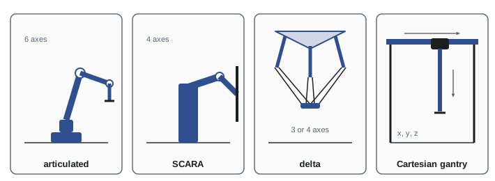
Articulated arms dominate the market because a six-axis arm can place a tool at any position and orientation within its envelope. A seventh axis, as on some collaborative and dual-arm robots, adds redundancy that helps avoid obstacles and singularities. Articulated arms are also commonly mounted on a linear track, called a seventh axis or range extender, to serve several machines.
SCARA stands for Selective Compliance Assembly Robot Arm. The arm is compliant in the horizontal plane but stiff vertically, which suits pushing a pin into a hole. Typical SCARA cycle times on the industry-standard test path are well under half a second.
Delta robots, invented by Reymond Clavel in the 1980s, hang from a frame above a conveyor. Because the motors are fixed to the frame and only light carbon-fibre arms move, they can exceed 10 g of acceleration and perform more than 150 picks a minute on light products.
Gantry robots are built from linear modules. Their envelope is a rectangular box, which matches pallets, machine beds and storage racks. Their accuracy is limited mainly by the rails and drives rather than by a chain of rotary joints, so large gantries can hold tight tolerances over several metres.
Reading a robot datasheet
A datasheet compresses a robot into a page of numbers. Integrators learn to read them sceptically, because each number is measured under specific conditions.
| Specification | What it means | Watch out for |
|---|---|---|
| Rated payload | Mass the robot can carry at rated speed and acceleration | Applies with the load centre of gravity inside a specified offset and inertia; the gripper counts as payload |
| Reach | Maximum distance from the base axis to the wrist centre point | Usable reach with a tool is smaller, and accuracy and payload fall near the edge |
| Pose repeatability | Spread of positions when returning to the same taught point (ISO 9283) | Not the same as accuracy; a robot can be repeatable to 0.02 mm and inaccurate by 1 mm |
| Pose accuracy | Difference between a commanded position and the position reached | Often not published; matters for offline programming and vision-guided moves |
| Axis speeds | Maximum angular speed of each joint | Real cycle time is limited by acceleration, payload and path, not top speed |
| Protection rating | Ingress protection code such as IP67 for the wrist | Body and wrist ratings can differ; food and foundry versions exist |
| Mounting | Floor, wall, ceiling or angled | Not all models allow every mounting; payload diagrams may change |
Repeatability and accuracy are often confused. ISO 9283 defines pose repeatability as the radius of a sphere that contains the measured positions when the robot returns many times to the same commanded pose, calculated as the mean distance from the centroid plus three standard deviations. Pose accuracy is the distance between the commanded pose and the centroid of the reached poses. A taught point relies on repeatability only, because the operator moved the robot to the real location and recorded the joint angles. A point calculated from a CAD model or from a camera relies on accuracy, which depends on how well the robot's kinematic model matches the real arm. Calibration, covered in Lesson 4, closes that gap.
Worked problem
Computing ISO 9283 pose repeatability
A robot returns 30 times to the same taught point. The distances of the measured positions from their centroid have a mean of 0.012 mm and a standard deviation of 0.004 mm. What repeatability figure would be reported?
Show solution
- ISO 9283 pose repeatability is \( RP = \bar{l} + 3 S_l \), where \( \bar{l} \) is the mean distance from the centroid and \( S_l \) its standard deviation.
- \( RP = 0.012 + 3 \times 0.004 = 0.024 \) mm.
- The datasheet would typically round this to ±0.02 or ±0.03 mm depending on the manufacturer's convention.
Answer: About 0.024 mm. This says nothing about how close the centroid is to the commanded point, which is accuracy.
# ISO 9283-style repeatability and accuracy from simulated measurements
import numpy as np
rng = np.random.default_rng(440)
commanded = np.array([800.0, 200.0, 500.0])            # mm, commanded position
bias = np.array([0.35, -0.20, 0.15])                   # systematic model error, mm
pts = commanded + bias + rng.normal(0, 0.006, size=(30, 3))
centroid = pts.mean(axis=0)
l = np.linalg.norm(pts - centroid, axis=1)
RP = l.mean() + 3 * l.std(ddof=1)
AP = np.linalg.norm(centroid - commanded)
print(f"repeatability RP = {RP:.3f} mm")
print(f"accuracy AP = {AP:.3f} mm")repeatability RP = 0.022 mm accuracy AP = 0.431 mm
Payload and wrist load diagrams
Rated payload alone is not enough. Every manufacturer publishes a load diagram that shows the permitted mass as a function of how far the load's centre of gravity sits from the tool flange, both along the flange axis and sideways. A robot rated for 20 kg may allow the full 20 kg only when the centre of gravity is within about 100 mm of the flange, and much less at 300 mm. The wrist motors also have limits on static torque and on moment of inertia about each wrist axis. Lesson 3 shows how to check a gripper and part against these limits. For now, the rule is that the payload includes everything mounted on the flange: tool changer, gripper, hoses, sensors and the heaviest part, with a margin for future changes.
Worked problem
Is the payload within the wrist torque limit?
A robot's datasheet allows a static wrist torque of 50 N·m about axis 5. A gripper of 6 kg with its centre of gravity 120 mm from the flange carries parts of 9 kg whose centre of gravity is 250 mm from the flange, on the same axis. Check the static torque with the arm horizontal.
Show solution
- Torque from the gripper: \( 6 \times 9.81 \times 0.120 \approx 7.1 \) N·m.
- Torque from the part: \( 9 \times 9.81 \times 0.250 \approx 22.1 \) N·m.
- Total: \( 7.1 + 22.1 = 29.2 \) N·m, which is 58 per cent of the 50 N·m limit.
- Dynamic torques during acceleration add to this, so a 30 to 40 per cent static margin is reasonable.
Answer: About 29 N·m, inside the limit with reasonable margin; the combined 15 kg must also be inside the load diagram at its combined centre of gravity.
Applications that dominate the market
Industrial robots are concentrated in a handful of applications. Handling, which includes machine tending, palletizing, packing and pick-and-place, is the largest category in IFR statistics, followed by welding and soldering, assembly, and dispensing and painting.
Arc welding robots carry a welding torch and wire feeder, often working with a positioner that rotates the part so that every weld is made in the flat position. Spot welding robots in automotive body shops carry heavy servo guns and are among the largest robots made. Painting robots are built with explosion-protected motors, or pressurized housings, so that they can operate in solvent-laden air, and use rotary bell atomizers with electrostatic charge to improve transfer efficiency. Machine tending robots load and unload CNC lathes, mills, presses and moulding machines, an application that grew rapidly with collaborative arms because many small shops have one or two machines and no room for a fenced cell. Palletizing robots stack cases at the end of packaging lines. Assembly robots insert, press, screw and snap components together, often with force sensing. Dispensing robots apply adhesives and sealants along a path whose speed must be tightly controlled for a consistent bead.
| Application | Common robot type | Key process concern | Typical tooling |
|---|---|---|---|
| Arc welding | Six-axis articulated, hollow wrist | Torch angle, travel speed, seam tracking | Torch, wire feeder, positioner, torch cleaner |
| Spot welding | Large six-axis articulated | Gun force, tip dressing, reach into body | Servo weld gun, tip dresser |
| Painting | Explosion-protected articulated | Film thickness, overspray, solvent atmosphere | Rotary bell atomizer, colour changer |
| Machine tending | Articulated or collaborative | Door interlocks, chip and coolant, part orientation | Dual gripper, air blow-off |
| Palletizing | Four-axis palletizer, articulated or gantry | Pattern, stability, cycle rate | Vacuum, clamp or fork tool |
| Assembly | SCARA or six-axis with force sensor | Tolerances, insertion forces | Screwdriver, press, compliant wrist |
| Picking from conveyors | Delta | Tracking moving parts, high rates | Suction cups, vision |
Each application drives the robot choice. Palletizers, for example, are often four-axis robots because the tool only needs to stay horizontal and rotate about a vertical axis; removing the wrist axes increases payload and speed for the same cost. A spot welding robot needs a large payload for the gun and a stiff structure to resist reaction forces. A painting robot needs a hollow wrist so that paint and air lines can run inside the arm without catching on the part.
Throughput: the first feasibility check
Before a detailed design, engineers estimate whether a robot can keep up. If a production line must produce a certain number of parts per shift, the available time divided by the required number of parts gives the takt time, the maximum time per part. The robot's cycle time must be shorter than takt, with margin for variation, faults and future growth.
Worked problem
Takt time for a machine tending cell
A plant needs 1,800 housings a day from a cell that runs two 8-hour shifts with two 15-minute breaks and a 30-minute lunch per shift, during which the cell stops. What is the takt time, and can a robot with a 38 s cycle meet it?
Show solution
- Available time per shift: \( 480 - 30 - 30 = 420 \) minutes; for two shifts, 840 minutes or 50,400 s.
- Takt: \( 50\,400 / 1800 = 28 \) s per part.
- A 38 s cycle is longer than 28 s, so one robot cannot meet demand as designed.
- Options include running through breaks (the robot does not need lunch), a second machine, a dual gripper to shorten exchange time, or a third shift.
Answer: Takt is 28 s; the 38 s cycle fails. If the cell runs through breaks, available time becomes 960 minutes and takt 32 s, which still fails, so the process itself must be shortened or parallelized.
# Quick feasibility: robots needed for a picking rate with variability
import numpy as np
rng = np.random.default_rng(440)
demand_per_min = 120            # products arriving per minute
pick_cycle_s = rng.normal(0.55, 0.06, 100_000)   # delta robot pick cycles, s
mean_rate = 60 / pick_cycle_s.mean()
p95_rate = 60 / np.percentile(pick_cycle_s, 95)
print(f"mean picks per robot per min: {mean_rate:.0f}")
print(f"rate at slow (95th pct) cycle: {p95_rate:.0f}")
for n in (1, 2, 3):
print(f"{n} robot(s): utilization {demand_per_min / (n * mean_rate):.0%}")mean picks per robot per min: 109 rate at slow (95th pct) cycle: 92 1 robot(s): utilization 110% 2 robot(s): utilization 55% 3 robot(s): utilization 37%
High utilization looks efficient on paper but leaves no room for slow cycles, missed picks or restarts after a fault. Planners commonly aim for 75 to 85 per cent utilization of the bottleneck robot, a rule of thumb that Lesson 10 justifies with availability and OEE numbers.
Market trends
Several trends shape industrial robotics in the mid-2020s. Collaborative applications continue to grow, particularly in small and medium enterprises. Vision and AI-based picking have made it practical to handle mixed parts that once required careful fixturing. Robot prices per unit have fallen while integration costs, including tooling, guarding, programming and commissioning, often make up two-thirds or more of total project cost. Offline programming and simulation, discussed in Lessons 2 and 4, are now standard for large projects. Labour shortages in manufacturing and logistics in both Canada and the United States have accelerated adoption, and government incentives for capital investment, covered in Lesson 11, affect the payback calculation. At the same time, many robots still perform the same welding and handling tasks that defined the field in the 1980s, and the fundamentals of reach, payload and cycle time have not changed.
Industrial robot density, the number of robots per 10,000 manufacturing employees, is a common international comparison. IFR reports have placed South Korea, Singapore, China, Germany and Japan near the top, with the United States and Canada lower but rising. Density reflects industry mix as much as policy: economies dominated by automotive and electronics manufacturing naturally have more robots.
Common mistakes
MistakeTreating rated payload as the mass of the part.
InsteadPayload includes the gripper, tool changer, hoses and sensors, and it is valid only within the load diagram.
MistakeAssuming repeatability guarantees accuracy.
InsteadRepeatability matters for taught points; offline and vision-guided points depend on accuracy and calibration.
MistakePicking a six-axis robot by habit for every job.
InsteadA SCARA, delta, palletizer or gantry may be faster, cheaper and stiffer for the task.
MistakeComparing cycle time with demand using total shift time.
InsteadSubtract planned stops to get takt, and keep margin for variation and faults.
MistakeQuoting maximum axis speeds as cycle-time evidence.
InsteadCycle time depends on acceleration, payload, path and settling; simulate or test.
Summary and key terms
- An industrial robot is an automatically controlled, reprogrammable, multipurpose manipulator programmable in three or more axes (ISO 8373).
- Articulated, SCARA, delta, Cartesian and collaborative robots each suit different reach, speed, payload and space requirements.
- Datasheet payload, reach, repeatability and speed are measured under specific conditions; load diagrams and wrist limits govern real tooling.
- ISO 9283 repeatability is mean distance from the centroid plus three standard deviations; accuracy is distance from the commanded pose.
- Handling, welding, assembly, painting and dispensing are the main applications, each with typical robot types and tooling.
- Takt time is available time divided by required output; the robot cycle must be comfortably shorter.
- Integration, not the robot arm, usually dominates total project cost.
- Industrial robot
- An automatically controlled, reprogrammable, multipurpose manipulator programmable in three or more axes.
- SCARA
- Selective Compliance Assembly Robot Arm, a four-axis robot compliant horizontally and stiff vertically.
- Delta robot
- A parallel robot with light arms driven from a fixed frame, used for very fast picking.
- Gantry robot
- A Cartesian robot built from linear axes on an overhead frame.
- Load diagram
- A chart of permitted payload mass against centre-of-gravity offset from the flange.
- Pose repeatability
- How closely a robot returns to the same commanded pose, per ISO 9283.
- Pose accuracy
- How close the reached pose is to the commanded pose.
- Takt time
- Available production time divided by required output.
- Fixed automation
- Dedicated equipment designed for one product or operation, fast but inflexible.
Practice problems
Work each problem on paper first, then reveal the answer to check.
Why do palletizing robots often have only four axes?
Show answer
The tool stays horizontal and rotates about a vertical axis, so dropping wrist axes raises payload and speed.
A SCARA or a six-axis arm for inserting pins vertically into circuit boards at high speed?
Show answer
A SCARA: fast in the plane and stiff vertically.
Mean distance 0.01 mm, standard deviation 0.003 mm: repeatability?
Show answer
\( 0.01 + 3(0.003) = 0.019 \) mm.
Two 7.5-hour shifts of production, 2,700 parts required: takt?
Show answer
\( 54\,000 / 2700 = 20 \) s.
What items count toward payload?
Show answer
Gripper, tool changer, sensors, hoses, adapter plates and the part.
Why are painting robots built differently from handling robots?
Show answer
They work in flammable solvent atmospheres and need explosion protection and hollow wrists for paint lines.
What is a range extender?
Show answer
A linear track that carries a robot to serve a larger area or several machines.
Give one reason a project might choose fixed automation over a robot.
Show answer
One product in very high volume where dedicated equipment is faster and cheaper.
Lesson quiz · 5 questions
Score 60% or more to complete this lesson.
Create a free account to save your progress, take quizzes and earn a certificate.