
ROB-440 · Lesson 12 of 12 · 39 min
Capstone: designing a palletizing cell
This capstone brings the course together in one design: an end-of-line robotic palletizing cell for a food manufacturer. Palletizing is one of the most common robot applications in both Canada and the United States, and it touches nearly every topic in ROB-440: choosing a robot type, designing a vacuum end effector and checking its payload, cycle-time analysis against takt, pallet pattern design, PLC sequencing and the robot handshake, networking and data reporting, safeguarding pallet exchange, maintenance planning and the business case. We work through the design step by step, as an integrator would for a concept proposal, then list the deliverables a complete design package would contain. The numbers are realistic but illustrative; a real project would confirm them with the customer's data, vendor tools and simulations.
Step 1: Requirements
The customer packs breakfast cereal into corrugated cases at the end of two packaging lines. Each line delivers up to 6 cases a minute, so the cell must handle up to 12 cases a minute combined. Cases measure 400 mm long, 300 mm wide and 250 mm high and weigh 12 kg. Each line runs a different product, so the two lines must be palletized onto separate pallets. Pallets are the North American standard 48 by 40 inch size, 1,219 by 1,016 mm. The customer's warehouse limits loaded pallet height, including the pallet, to 1.8 m, and the pallet itself is 150 mm high. The plant runs three 8-hour shifts, five days a week. Forklift drivers remove full pallets and bring empty ones. Today, two workers per shift stack cases by hand, a task that has caused back injuries. The customer wants a payback of under three years.
| Requirement | Value | Design consequence |
|---|---|---|
| Case size and mass | 400 × 300 × 250 mm, 12 kg | Vacuum tool sized for corrugated board; payload per pick |
| Combined rate | 12 cases per minute from two lines | Takt of 5 s per case for one robot |
| Products | Two, one per line, separate pallets | Two build stations, one per line |
| Pallet | 1,219 × 1,016 mm, 150 mm high | Pattern design, robot reach |
| Maximum load height | 1.8 m including pallet | Number of layers and vertical reach |
| Pallet exchange | By forklift, without stopping the robot | Safeguarding that allows forklifts but detects people |
| Payback | Under 3 years | Cost control and realistic savings |
Step 2: Pallet pattern
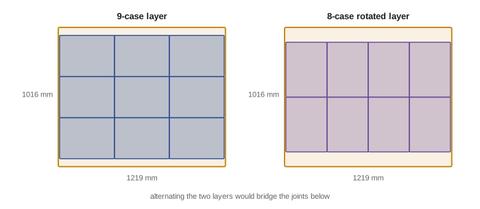
The pallet pattern determines how many cases fit per layer and per pallet, the stability of the load, and the robot's motions. Cases are usually interlocked: alternate layers are rotated or mirrored so that cases bridge the joints of the layer below, like bricks in a wall. A good pattern uses as much of the pallet area as possible without overhanging its edges, since overhang damages cases in transport.
Worked problem
Cases per layer and per pallet
Find how many 400 × 300 mm cases fit in one layer on a 1,219 × 1,016 mm pallet without overhang, and how many layers fit under the 1.8 m height limit.
Show solution
- With the 400 mm side along the 1,219 mm edge: \( \lfloor 1219/400 \rfloor = 3 \) and \( \lfloor 1016/300 \rfloor = 3 \), giving 9 cases.
- Rotated: \( \lfloor 1219/300 \rfloor = 4 \) and \( \lfloor 1016/400 \rfloor = 2 \), giving 8 cases, leaving a 216 mm strip that could hold rotated cases in a mixed pattern only if they fit: \( 1016 - 800 = 216 \) mm is less than 300 mm, so no.
- So 9 cases per layer, covering \( 9 \times 0.12 = 1.08 \) m² of the \( 1.239 \) m² pallet, about 87 per cent.
- Height available for cases: \( 1800 - 150 = 1650 \) mm, so \( \lfloor 1650/250 \rfloor = 6 \) layers.
- Cases per pallet: \( 6 \times 9 = 54 \), with a load of \( 54 \times 12 = 648 \) kg plus the pallet.
Answer: 9 cases per layer and 6 layers, 54 cases per pallet. Identical 3 by 3 layers stack in columns, which are less stable than interlocked layers, so the design either relies on stretch wrapping and a tie sheet at mid-height, or alternates with the rotated 8-case layer, giving 51 cases per pallet. Here the customer accepts columns with a tie sheet to keep 54.
# Search simple block patterns for cases per layer on a pallet (no overhang)
from itertools import product
pallet = (1219, 1016)          # mm
case = (400, 300)              # mm
best = []
for a_len, a_wid in (case, case[::-1]):        # orientation of the main block
    for n1 in range(0, pallet[0] // a_len + 1):
        rest = pallet[0] - n1 * a_len               # strip left along the long edge
        main = n1 * (pallet[1] // a_wid)
        side = (rest // a_wid) * (pallet[1] // a_len)   # rotated cases in the remaining strip
        best.append((main + side, n1, (a_len, a_wid)))
best.sort(reverse=True)
count, n1, orient = best[0]
print(f"best simple two-block pattern: {count} cases per layer (main block {n1} columns of {orient})")
print(f"area use: {count * case[0] * case[1] / (pallet[0] * pallet[1]):.0%}")best simple two-block pattern: 9 cases per layer (main block 3 columns of (400, 300)) area use: 87%
Step 3: Robot and cell layout
Several robot types could do this job. A four-axis articulated palletizing robot is the classic choice: high payload, fast, and the tool only needs to stay horizontal and rotate. A collaborative robot on a column lift could suit a single, slower line but would struggle with 12 cases a minute at 12 kg each. A gantry would work but occupies more floor space and height. We choose a four-axis palletizer serving two build stations side by side, one per line, with conveyors bringing cases from each line to a pick position between them.
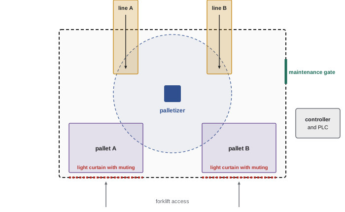
The robot must reach the farthest corner of each pallet at the lowest layer and at the top layer with the tool fitted. With the robot base centred between pallets and about 1.6 m from each pallet's far corner, and the top of the stack 1.8 m above the floor, a palletizer with around 3 m reach and a vertical stroke covering the floor-level first layer to the top of the stack plus the tool's height is appropriate. A simulation confirms reach and checks that the arm clears the conveyors and fence.
Worked problem
Payload check for picking two cases
To meet the rate comfortably, the tool will pick two cases at a time from the same line when possible. The vacuum tool weighs 38 kg with its centre of gravity 180 mm below the flange; two cases weigh 24 kg with their centre of gravity 380 mm below the flange. Is a palletizer rated for 110 kg with a permitted centre-of-gravity offset of 400 mm at that payload suitable?
Show solution
- Total payload: \( 38 + 24 = 62 \) kg.
- Combined centre of gravity: \( (38 \times 180 + 24 \times 380)/62 = (6840 + 9120)/62 \approx 257 \) mm below the flange.
- 62 kg at 257 mm is well inside the 110 kg at 400 mm envelope.
- Vacuum force check, from Lesson 3: two pads of 0.04 m² at 25 kPa give 2,000 N against \( 2 \times 2 \times 12 \times 14.81 \approx 711 \) N required with a safety factor of 2 at 5 m/s².
Answer: Yes; the robot has ample payload margin, which also allows a future product in heavier cases. The tool needs one vacuum zone per case so that a single case can be placed alone.
Step 4: Cycle time
The takt for one robot serving both lines is 5 s per case at the combined peak of 12 cases a minute. Picking two cases at a time halves the number of robot cycles if cases arrive in pairs. A sequence chart with the robot vendor's simulation gives a typical pick-and-place cycle, from pick position to a place point on the pallet and back, of about 6.5 s for a double pick at mid-stack height, longer for the far corners and shorter for near positions.
Worked problem
Can one robot keep up?
The robot performs double picks averaging 6.5 s per cycle. Ten per cent of cycles must be single picks, for example at the end of a layer or when one line is slow, averaging 5.5 s. Every 54 cases the robot must also place a slip sheet on an empty pallet, taking 9 s. What is the average time per case, and what utilization does it give at 12 cases a minute?
Show solution
- In 100 cycles: 90 double picks move 180 cases in \( 90 \times 6.5 = 585 \) s; 10 single picks move 10 cases in 55 s.
- Cases moved: 190 in 640 s, or about 3.37 s per case.
- Slip sheets: one per 54 cases, adding \( 9/54 \approx 0.17 \) s per case, for 3.54 s per case.
- Utilization at 5 s takt: \( 3.54 / 5 \approx 71 \) per cent.
Answer: About 3.5 s per case, 71 per cent utilization at peak, leaving margin for slow cycles, recovery and future growth.
# Cases that accumulate on one line while its station waits for a forklift exchange
import numpy as np
rng = np.random.default_rng(440)
rate = 6 / 60                     # cases per second from one line
exchange_s = 60                   # time to swap pallets once the forklift arrives
for mean_delay in (60, 180, 300):
    wait = rng.exponential(mean_delay, 100_000) + exchange_s      # station blocked, s
    cases = rng.poisson(rate * wait)                              # arrivals while blocked
    p95, p99 = np.percentile(cases, [95, 99])
    print(f"mean forklift delay {mean_delay:3d} s: 95% of exchanges need <= {p95:3.0f} cases "
f"({p95 * 0.4:4.1f} m), 99% need <= {p99:3.0f} cases ({p99 * 0.4:4.1f} m)")mean forklift delay 60 s: 95% of exchanges need <= 25 cases (10.0 m), 99% need <= 36 cases (14.4 m) mean forklift delay 180 s: 95% of exchanges need <= 61 cases (24.4 m), 99% need <= 91 cases (36.4 m) mean forklift delay 300 s: 95% of exchanges need <= 97 cases (38.8 m), 99% need <= 147 cases (58.8 m)
The simulation shows a common palletizing issue: if a forklift is late to exchange a full pallet, cases accumulate on the conveyor. At 6 cases a minute, every extra minute of delay needs about 6 cases of buffer, roughly 2.4 m of conveyor for 400 mm cases, and because delays have a long tail, covering the occasional very late forklift with conveyor alone becomes impractical when drivers are busy. Many cells therefore add an automatic empty-pallet dispenser and a full-pallet outfeed conveyor holding two or three loads, so that the robot never waits for a forklift and drivers can collect pallets when convenient. With that arrangement, the light curtains move to the outfeed conveyor's exit, which simplifies the safeguarding discussed in Step 6.
Step 5: Controls and integration
A PLC coordinates the cell. It controls the infeed conveyors and their accumulation zones, reads photo-eyes that confirm cases at the pick position, tells the robot which line and which pattern position to serve through the handshake described in Lesson 5, monitors vacuum levels through IO-Link switches, tracks case counts per pallet, and signals forklift drivers through stack lights and the plant's warehouse system when a pallet is full. Recipes for each product store the case dimensions, pattern and layer count, so that a new product is added by entering data rather than reprogramming the robot, using the palletizing software that most robot vendors provide.
| Signal or data | Source | Destination | Purpose |
|---|---|---|---|
| Case present at pick, line A and B | Photo-eyes | PLC | Start a pick only when cases are in place |
| Job: line, pattern position, single or double pick | PLC | Robot | Tell the robot what to do next |
| Busy, done, at home, fault code | Robot | PLC | Four-phase handshake and diagnostics |
| Vacuum level per zone | IO-Link switches | PLC and robot | Confirm grip before moving; monitor cup wear |
| Pallet full, pallet present | PLC and sensors | Stack light, WMS | Call forklift; record pallet ID |
| Cases per hour, OEE, faults | PLC | OPC UA server, MQTT | Dashboard and maintenance analytics |
Each finished pallet receives a label with a serial shipping container code, which links it in the warehouse management system to the product, lot and date, supporting food traceability requirements. The cell publishes production counts, OEE losses and fault codes to the plant's data system, following the naming conventions of the plant's namespace as described in Lesson 6, and the cell's network sits in its own security zone behind the plant firewall.
Step 6: Safeguarding
The hardest safeguarding problem in palletizing is pallet exchange: forklifts must enter the pallet stations, but people must not walk in while the robot is working there. The classic solution is a light curtain across each pallet station opening with muting: additional sensors recognize the pattern of a pallet or forklift passing through, and the safety controller temporarily mutes the light curtain only for that pattern, while a person walking through triggers a stop. Muting must be designed carefully so that a person cannot walk in beside or on the pallet, and the muting sensors must be placed so that they are triggered in the right sequence only by the load. An alternative is to let the robot keep working at the other station while the exchange station's opening is open, using safety-rated zone limiting so that the robot cannot enter the open station, which keeps the robot productive during exchanges.
Worked problem
Light curtain distance at the pallet station
The pallet station opening is guarded by a vertical light curtain with a 30 mm resolution. The robot's measured worst-case stopping time is 0.55 s, and the light curtain and safety PLC add 0.03 s. Using the ISO 13855 relation from ROB-430, \( S = KT + C \) with \( C = 8(d - 14) \) mm, how far must the light curtain be from the nearest point the robot can reach in that station?
Show solution
- Overall stopping time: \( T = 0.58 \) s; intrusion term \( C = 8(30 - 14) = 128 \) mm.
- With \( K = 2000 \) mm/s: \( S = 1160 + 128 = 1288 \) mm, which exceeds 500 mm.
- Recalculate with \( K = 1600 \) mm/s: \( S = 928 + 128 = 1056 \) mm, still above 500 mm, so 1,056 mm applies.
- If safety-rated zone limiting keeps the robot out of a station whose curtain is interrupted, this distance applies from the curtain to the boundary of the limited zone, not to the far side of the station.
Answer: About 1.06 m, using the classic form of the formula; confirm with the current edition of ISO 13855 and the manufacturer's data, and verify the stopping time on the real robot.
The risk assessment follows ISO 12100 and CSA Z434:26. For the gate used by maintenance staff to enter the cell, the analysis in Lesson 8 gives a high required performance level, so the gate uses a coded interlock with guard locking wired to a safety PLC, and the robot's safety stop input achieves the required PL. In Ontario, the use of light curtains with muting in place of a physical guard may trigger a pre-start health and safety review under section 7 of Regulation 851, which must be planned into the schedule. Lockout procedures for the robot, conveyors and vacuum supply follow provincial requirements and CSA Z460.
Step 7: Maintenance and reliability
The maintenance plan lists preventive tasks from the robot manual, such as gearbox lubrication intervals, encoder battery replacement and cable inspection, plus cell-specific tasks: inspecting and replacing vacuum pads, cleaning vacuum filters, which clog with corrugated board dust, checking photo-eye alignment, and verifying light curtain and muting function with a test procedure at each shift start. Condition monitoring uses vacuum build-up time per zone and the robot's axis torque trends, as Lesson 10 described. Spare parts kept on site include vacuum pads and filters, a vacuum generator, photo-eyes, a muting sensor set, and a spare tool if the plant has no other way to keep running during a tool failure.
Worked problem
Expected availability
Estimates for the cell are: robot MTBF 50,000 h, MTTR 6 h; vacuum tool MTBF 2,000 h, MTTR 0.5 h; two conveyors each MTBF 4,000 h, MTTR 1 h; light curtain and muting MTBF 10,000 h, MTTR 1 h. What inherent availability results, and what does it mean for output?
Show solution
- Robot: \( 50\,000/50\,006 \approx 0.99988 \); tool: \( 2000/2000.5 \approx 0.99975 \).
- Each conveyor: \( 4000/4001 \approx 0.99975 \), so both together about 0.99950.
- Light curtain system: \( 10\,000/10\,001 \approx 0.99990 \).
- Product: \( \approx 0.9990 \), or 99.9 per cent from failures alone.
- The real availability will be lower, because forklift delays, upstream starvation, case quality problems and changeovers dominate in palletizing.
Answer: About 99.9 per cent inherent availability; planning should focus on pallet logistics and case quality, which usually cause more lost time than equipment failures.
Step 8: The business case
An integrator's budgetary estimate for this cell might be around $520,000, including the palletizer, vacuum tool, conveyors and accumulation, pallet station sensors, safeguarding, controls, engineering, installation and training, plus a 10 per cent contingency. The cell replaces two workers per shift on three shifts, five days a week. Using a fully loaded labour cost of $34 an hour and 250 working days, the labour saving is about $408,000 a year; subtracting a technician's time, energy, vacuum pads and service of perhaps $45,000 a year, and adding avoided injury costs of $15,000, the net saving is roughly $378,000 a year. Simple payback is about 1.4 years, well inside the customer's target, and the after-tax position improves further with the first-year write-offs described in Lesson 11, subject to current rules and professional advice.
Worked problem
Sensitivity to staffing assumptions
Suppose the plant redeploys rather than reduces staff, and the realistic saving is only the avoided cost of hiring for one of the two positions per shift, so labour savings fall to half, about $204,000 a year. Using the same other costs, what is the payback?
Show solution
- Net saving: \( 204\,000 - 45\,000 + 15\,000 = \$174\,000 \) per year.
- Payback: \( 520\,000 / 174\,000 \approx 3.0 \) years.
- This just reaches the three-year target, showing that the staffing assumption, not the robot, decides the business case.
Answer: About 3 years. The proposal should state the staffing assumption explicitly and show both cases.
Step 9: The design package
A complete concept and detailed design for this cell would include the following deliverables, which together demonstrate the skills of the whole course.
| Deliverable | Content | Lesson |
|---|---|---|
| Requirements and specification | URS, functional design specification, acceptance criteria | 2, 11 |
| Robot selection and layout | Robot comparison, layout drawing, reach and interference simulation | 1, 2 |
| End effector design | Vacuum tool concept, payload data, vacuum calculations, behaviour on air loss | 3 |
| Programs and patterns | Pattern definitions, robot program structure, recovery routines | 4 |
| Control design | PLC state machine, robot handshake specification, HMI screens, recipes | 5 |
| Network and data | Network architecture, security zone, OPC UA or MQTT data model | 6 |
| Vision (if required) | Case orientation or label checks, lighting and resolution | 7 |
| Safety | Risk assessment, safety functions with PLr and achieved PL, distances, validation plan | 8 |
| Logistics interface | Pallet exchange, buffers, forklift or conveyor handling, WMS link | 9 |
| Maintenance plan | Preventive tasks, condition monitoring, spare parts list, OEE reporting | 10 |
| Business case and project plan | Cost estimate, savings, payback, NPV, schedule with FAT, SAT and run-off | 11 |
Working through a design like this shows how strongly the parts depend on each other. Picking two cases at a time changed the tool, the payload, the cycle time and the vacuum zones. Letting the robot keep working during pallet exchange changed the safeguarding, the safety functions and the throughput. The customer's staffing plan changed the payback more than any technical choice. Industrial robotics rewards engineers who can hold the whole system in view.
Common mistakes
MistakeDesigning the robot motion before the pallet pattern and logistics.
InsteadFix the pattern, pallet exchange and buffers first; they drive layout, cycle and safety.
MistakeUsing one vacuum zone for a multi-case tool.
InsteadProvide a zone per case so that single cases can be placed and partial grips detected.
MistakeMuting a light curtain with poorly placed sensors.
InsteadDesign muting so that only the load pattern mutes it, in sequence, and a person beside the load is detected.
MistakeIgnoring forklift timing.
InsteadSize accumulation buffers or add pallet dispensers and outfeed conveyors.
MistakeHiding the staffing assumption in the business case.
InsteadState it explicitly and show sensitivity to it.
Summary and key terms
- The capstone designs a two-line palletizing cell at 12 cases a minute, 9 cases per layer and 6 layers per pallet.
- A four-axis palletizer with a two-zone vacuum tool meets payload and rate with about 71 per cent utilization at peak.
- Pallet exchange and accumulation buffers, not robot speed, often limit palletizing throughput.
- A PLC state machine, robot handshake, recipes, IO-Link vacuum monitoring and OPC UA or MQTT reporting integrate the cell.
- Light curtains with muting, or safety-rated zone limiting, allow forklift exchange while protecting people.
- Maintenance focuses on vacuum pads, filters, sensors and safety checks, with condition monitoring.
- The business case depends heavily on staffing assumptions; a complete design package covers every lesson of the course.
- Palletizing
- Stacking cases or products onto pallets in a defined pattern.
- Interlocked pattern
- A pallet pattern in which alternate layers are arranged so that cases bridge joints below.
- Slip sheet
- A sheet placed on a pallet or between layers to improve stability or protect products.
- Muting
- Temporary, automatic suspension of a protective device while a recognized load passes.
- Accumulation conveyor
- A conveyor that holds a queue of products as a buffer.
- Vacuum zone
- A separately controlled section of a vacuum tool.
- Recipe
- A stored set of product parameters used to configure a cell.
- Serial shipping container code
- A standard identifier on pallet labels used for logistics traceability.
Practice problems
Work each problem on paper first, then reveal the answer to check.
Cases 500 × 300 mm on a 1,219 × 1,016 mm pallet with 500 along the long edge: cases per layer?
Show answer
\( 2 \times 3 = 6 \) cases.
Stack height limit 1.6 m, pallet 150 mm, cases 300 mm high: layers?
Show answer
\( \lfloor 1450/300 \rfloor = 4 \).
Takt for 15 cases a minute?
Show answer
4 s per case.
Tool 30 kg at 150 mm and cases 20 kg at 350 mm: combined centre of gravity?
Show answer
\( (4500 + 7000)/50 = 230 \) mm.
Forklift delay of 3 minutes at 6 cases a minute: buffer needed?
Show answer
18 cases.
What does muting allow?
Show answer
A recognized load such as a pallet to pass a light curtain without stopping the robot.
Name two condition indicators for this cell.
Show answer
Vacuum build-up time per zone and axis torque trends.
Investment $520,000 and savings $260,000 a year: payback?
Show answer
2 years.
Lesson quiz · 5 questions
Score 60% or more to complete this lesson.
Create a free account to save your progress, take quizzes and earn a certificate.