
ROB-200 · Lesson 7 of 12 · 29 min
Timers, PWM and servo control
Timing is the heartbeat of robot control. Control loops must run at precise intervals, motors are driven by pulses whose width encodes how hard to push, hobby servos read their target angle from the length of a pulse repeated fifty times a second, and speed is measured by timing the gaps between encoder edges. Microcontrollers do all of this with hardware timers: counters that tick from a clock and trigger events at chosen counts, entirely without software once configured. This lesson explains how timers work, how they generate pulse-width modulation (PWM), how to choose PWM frequency and resolution for motors, LEDs and servos, and how timers capture inputs and decode encoders.
How a hardware timer works
A timer is a counter driven by a clock. The clock is usually the microcontroller's peripheral clock divided by a prescaler. The counter counts up from zero to a value in the auto-reload register, often called ARR or TOP, then returns to zero and starts again, generating an update event and optionally an interrupt each time. The timer's period is therefore set by the clock, the prescaler and the reload value:
The plus ones appear because counting from 0 to ARR takes ARR + 1 ticks, and a prescaler setting of 0 divides by 1; these off-by-one details are a frequent source of slightly wrong frequencies. A timer that interrupts every millisecond provides the tick for a control loop or a scheduler. Each timer also has several capture/compare channels. In compare mode, a channel watches the counter and changes an output pin or fires an interrupt when the count matches its compare register. In capture mode, it copies the counter value into a register when an input edge arrives, recording the edge's exact time.
Worked problem
Configuring a 1 kHz control-loop tick
A timer runs from a 72 MHz clock and has a 16-bit counter (maximum ARR 65,535). Choose PSC and ARR for exactly 1 kHz.
Show solution
- The total division needed is \( 72\,000\,000 / 1000 = 72\,000 \).
- That exceeds 65,536, so the prescaler must share the work.
- Choose PSC = 71, dividing by 72 to give a 1 MHz count rate (1 µs per tick).
- Then ARR = 999 gives \( 1\,000\,000 / 1000 = 1 \) kHz exactly.
Answer: PSC = 71 and ARR = 999. A 1 µs tick also makes it easy to read elapsed time in microseconds.
Pulse-width modulation
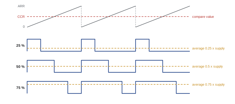
PWM switches an output fully on and fully off at a fixed frequency and varies the fraction of each period it spends on, the duty cycle. Because a switch that is fully on or fully off wastes almost no power, as lesson 3 showed, PWM is how microcontrollers control power efficiently. A motor, a heater or an LED responds to the average: an inductive motor winding smooths the current, the thermal mass of a heater smooths its temperature, and the eye smooths the flicker of an LED above about 100 to 200 Hz. The average voltage is the supply multiplied by the duty cycle:
In hardware, a timer channel in PWM mode sets its output high at the start of each period and low when the counter reaches the compare value (CCR). Changing CCR changes the duty cycle on the next period, with no further work from the processor. The number of distinct duty-cycle steps, the PWM resolution, is ARR + 1, so there is a trade-off: for a given timer clock, a higher PWM frequency means a smaller ARR and coarser steps.
def pwm_setup(f_clk, f_pwm, psc=0):
    arr = round(f_clk / ((psc + 1) * f_pwm)) - 1
    actual = f_clk / ((psc + 1) * (arr + 1))
    return arr, actual

f_clk = 72_000_000
for f in (50, 1_000, 20_000, 100_000):
    psc = {50: 21, 1_000: 1}.get(f, 0)  # low rates need a prescaler (16-bit ARR)
    arr, actual = pwm_setup(f_clk, f, psc)
    steps = arr + 1
    print(f"{f:7d} Hz: PSC {psc:3d} ARR {arr:6d} -> {actual:10.2f} Hz, "
f"{steps:6d} steps ({steps.bit_length()-1} bits)")50 Hz: PSC 21 ARR 65454 -> 50.00 Hz, 65455 steps (15 bits) 1000 Hz: PSC 1 ARR 35999 -> 1000.00 Hz, 36000 steps (15 bits) 20000 Hz: PSC 0 ARR 3599 -> 20000.00 Hz, 3600 steps (11 bits) 100000 Hz: PSC 0 ARR 719 -> 100000.00 Hz, 720 steps (9 bits)
Choosing a PWM frequency
The right frequency depends on the load. For DC motors, frequencies in the audible range make the motor whine, so drives commonly run at 16 to 25 kHz, above most people's hearing. The motor's electrical time constant, its inductance divided by its resistance, also matters: if the PWM period is long compared with it, current rises and falls a lot within each cycle, causing ripple, extra heating and torque pulsation. Higher frequencies smooth the current but increase the switching losses in the driver's MOSFETs, which are proportional to frequency. For LEDs, anything above a few hundred hertz avoids visible flicker, though cameras with fast shutters may still show banding below a few kilohertz. Heaters, with time constants of seconds, can use PWM periods of a second or more.
| Load | Typical PWM frequency | Why |
|---|---|---|
| Brushed DC motor | 16 to 25 kHz | Inaudible; smooths current through the winding inductance |
| Brushless motor (field-oriented control) | 10 to 40 kHz | Balances current ripple against switching losses |
| LED dimming | 500 Hz to 25 kHz | No visible flicker; higher for cameras |
| Hobby servo signal | 50 Hz (some digital servos up to about 330 Hz) | Convention set by radio-control systems |
| Heater or thermal element | 0.1 to 10 Hz | Long thermal time constant |
| Solenoid hold current | 1 to 20 kHz | Reduce holding power after a full-power pull-in |
Worked problem
Average voltage and speed
A 12 V motor driven at 20 kHz from a timer with ARR = 3,599 should receive an average of 7.5 V. What compare value is needed, and how fine is the speed control?
Show solution
- Duty cycle: \( D = 7.5 / 12 = 0.625 \).
- CCR \( = D \times (\text{ARR} + 1) = 0.625 \times 3600 = 2250 \).
- Resolution: one step is \( 12 / 3600 \approx 3.3 \) mV of average voltage, far finer than the motor can respond to.
Answer: CCR = 2,250. In practice the motor's speed also depends on load, so a feedback loop adjusts the duty cycle, as ROB-300 explains.
Hobby servos
A hobby servo combines a small DC motor, a gearbox, a potentiometer or magnetic sensor on the output shaft and a control circuit in one housing. It reads a pulse repeated about every 20 ms (50 Hz): a 1.5 ms pulse commands the centre position, and the range of about 1.0 to 2.0 ms spans the travel, commonly ±45 to ±90 degrees depending on the model. Many servos accept 0.5 to 2.5 ms for a wider range, but driving beyond a particular servo's mechanical limits makes it stall against its end stops, drawing high current and overheating. Continuous-rotation servos use the same signal to set speed and direction instead of position.
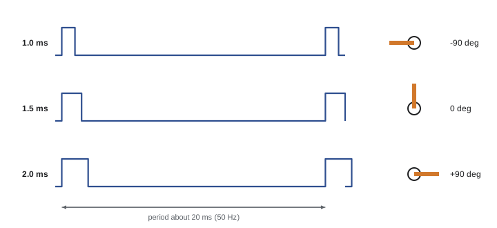
With a 50 Hz timer, the 1 ms span of useful pulse widths is only 5 % of the period, so resolution matters. A timer with a 1 µs tick and ARR = 19,999 gives 1,000 steps across the 1 ms range, roughly 0.18 degrees per step for a 180-degree servo, which is better than most hobby servos can position. Servos draw large current spikes when they move, often over 1 A each for standard sizes, so they need their own 5 to 7.4 V supply rated for the total stall current, with a shared ground but not the microcontroller's regulator. Larger robots use smart servos that communicate over a serial bus, report position, temperature and load, and can be daisy-chained, which ROB-220 covers.
def servo_ccr(angle_deg, min_us=1000, max_us=2000, span_deg=180, tick_us=1):
    """Compare value for a servo angle from -span/2 to +span/2."""
    frac = (angle_deg + span_deg / 2) / span_deg
    pulse_us = min_us + frac * (max_us - min_us)
    return round(pulse_us / tick_us), pulse_us

for a in (-90, -45, 0, 30, 90):
    ccr, us = servo_ccr(a)
print(f"{a:4d} deg -> pulse {us:6.1f} us, CCR = {ccr}")-90 deg -> pulse 1000.0 us, CCR = 1000 -45 deg -> pulse 1250.0 us, CCR = 1250 0 deg -> pulse 1500.0 us, CCR = 1500 30 deg -> pulse 1666.7 us, CCR = 1667 90 deg -> pulse 2000.0 us, CCR = 2000
Input capture: measuring time and speed
In capture mode, a timer records the exact count at which an input edge arrives, so the processor can calculate intervals with the timer's resolution rather than the uncertainty of software. Robots use this to measure the period of encoder or Hall-sensor pulses at low speed, to decode radio-control receiver pulses, to time ultrasonic echoes and to measure PWM signals from sensors that encode their output as a duty cycle.
There are two ways to measure speed from an encoder. Counting edges in a fixed time window, the frequency method, works well at high speed but becomes coarse at low speed, where only a few edges arrive per window. Timing the interval between edges, the period method, is precise at low speed but gives fewer, less frequent updates at high speed. Good motor controllers combine them, switching between methods or using both. In each case, the speed is the angle per count divided by the time.
Worked problem
Speed from captured edge times
A wheel encoder gives 2,048 counts per wheel revolution after 4× decoding. A timer with a 1 µs tick captures successive edges 1,220 ticks apart. How fast is the wheel turning, and how fast is the robot moving if the wheel diameter is 0.15 m?
Show solution
- Angle per count: \( 360 / 2048 \approx 0.176^\circ \).
- Time per count: 1.22 ms, so counts per second \( = 1/0.00122 \approx 820 \).
- Revolutions per second: \( 820/2048 \approx 0.40 \), or 24 rpm.
- Speed: \( 0.40 \times \pi \times 0.15 \approx 0.19 \) m/s.
Answer: About 24 rpm and 0.19 m/s. With the frequency method and a 10 ms window, only about 8 edges would arrive, giving a speed resolution of about 12 %.
Hardware encoder mode and complementary outputs
Many timers have an encoder interface mode in which the A and B channels drive the counter directly: it counts up for one direction and down for the other, in hardware, at millions of edges per second, with no interrupts. Software simply reads the count, at the control-loop rate, and takes the difference since the last read. This is the standard way to read motor encoders, as lesson 6 recommended.
Advanced timers designed for motor control add complementary outputs, pairs of PWM signals that are inverses of each other for driving the high-side and low-side switches of a half-bridge, with programmable dead time, a short gap when both are off so the two switches never conduct together and short the supply. They also have break inputs that force all outputs to a safe state within nanoseconds when a fault signal arrives, independent of software. Lesson 11 shows how these drive an H-bridge.
Common mistakes
MistakeForgetting the plus-one terms when calculating timer frequency.
InsteadUse f = fclk / ((PSC + 1)(ARR + 1)) and check the result on an oscilloscope.
MistakeDriving DC motors with PWM at 1 to 5 kHz.
InsteadUse 16 to 25 kHz to avoid audible whine and reduce current ripple, within the driver's ratings.
MistakeTreating servo position as a PWM duty cycle.
InsteadServos read pulse width, typically 1 to 2 ms, repeated at about 50 Hz.
MistakePowering servos from the microcontroller's regulator.
InsteadUse a separate supply rated for the total stall current, sharing ground.
MistakeMeasuring low speeds by counting edges in a short window.
InsteadTime the interval between edges with input capture, or combine both methods.
Summary and key terms
- Hardware timers count clock ticks; f = fclk / ((PSC + 1)(ARR + 1)) sets the period.
- Compare channels generate PWM; capture channels record exact edge times.
- PWM controls average voltage, Vavg = D × Vsupply, efficiently with fully on and off switching.
- Higher PWM frequency means fewer resolution steps for a given clock; motors typically use 16 to 25 kHz.
- Hobby servos read a 1 to 2 ms pulse every 20 ms; give them their own supply.
- Input capture and hardware encoder modes measure speed and position without CPU load.
- Motor-control timers provide complementary outputs with dead time and fast hardware break inputs.
- Prescaler
- A divider that reduces the clock rate feeding a timer's counter.
- Auto-reload register
- The value at which a timer counter restarts, setting its period.
- Capture/compare channel
- A timer unit that records counts on input edges or acts when the count matches a value.
- PWM
- Pulse-width modulation, controlling average power by varying the on-time of a fixed-frequency signal.
- Duty cycle
- The fraction of each period that a PWM signal is on.
- PWM resolution
- The number of distinct duty-cycle steps available.
- Hobby servo
- A motor, gearbox, position sensor and controller that move to an angle set by pulse width.
- Input capture
- Recording the timer count at the moment of an input edge.
- Encoder mode
- A timer configuration that counts quadrature encoder edges in hardware.
- Dead time
- A short interval when both switches of a half-bridge are off, preventing shoot-through.
Practice problems
Work each problem on paper first, then reveal the answer to check.
A timer clock is 48 MHz, PSC = 47, ARR = 1,999. What is the timer frequency?
Show answer
48 MHz / 48 / 2,000 = 500 Hz.
What duty cycle gives 9 V average from a 24 V supply?
Show answer
37.5 %.
With ARR = 999, what CCR gives 25 % duty cycle?
Show answer
250.
A 72 MHz timer with no prescaler runs PWM at 36 kHz. How many steps of resolution are there?
Show answer
2,000 (about 11 bits).
Why do motor drives often run PWM near 20 kHz?
Show answer
It is above most people's hearing and smooths current, while keeping switching losses moderate.
What pulse width commands the centre of a typical hobby servo?
Show answer
About 1.5 ms.
A servo timer has a 0.5 µs tick. What CCR gives a 1.2 ms pulse?
Show answer
2,400.
Captured encoder edges are 400 µs apart with 1,000 counts per revolution. What is the speed in rpm?
Show answer
2,500 counts/s ÷ 1,000 × 60 = 150 rpm.
What problem does dead time prevent?
Show answer
Shoot-through: both switches of a half-bridge conducting at once and shorting the supply.
What is a timer break input for?
Show answer
Forcing PWM outputs to a safe state immediately when a fault signal arrives.
Lesson quiz · 5 questions
Score 60% or more to complete this lesson.
Create a free account to save your progress, take quizzes and earn a certificate.