
ROB-200 · Lesson 5 of 12 · 25 min
Microcontrollers and embedded C
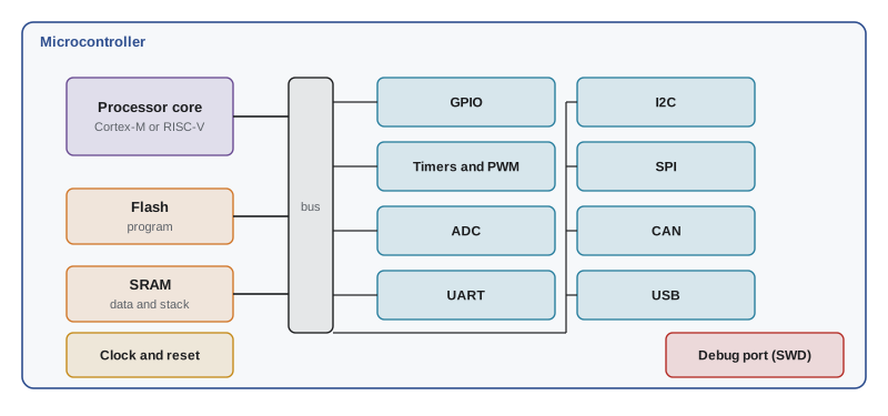
A microcontroller is a complete small computer on one chip: a processor core, flash memory for the program, RAM for data, and a collection of peripherals such as timers, analogue-to-digital converters and serial interfaces, all wired to the chip's pins. Unlike the Linux computer that runs ROS 2 on a robot, a microcontroller runs one program directly on the hardware, starts in milliseconds, responds to events in microseconds and costs from under a dollar to a few dollars. Almost every robot has several: in the motor drivers, the battery management system, the servos, the sensors and the main controller board. This lesson explains what is inside a microcontroller, how its memory is organized, how programs are written, built and loaded, and the features of the C language that matter most when code talks to hardware.
Microcontroller or single-board computer?
Robots usually pair the two. A single-board computer, such as a Raspberry Pi or an NVIDIA Jetson, runs Linux and ROS 2 and handles perception, planning and networking, but Linux cannot guarantee that a task runs every millisecond, and a board that takes 30 seconds to boot is a poor place for a safety interlock. A microcontroller handles the hard real-time work: generating motor PWM, reading encoders at high speed, closing current and velocity loops, and enforcing limits. The two talk over a serial link, USB, CAN or Ethernet. Some new boards put both on one board, for example combining a Linux-capable processor with a separate microcontroller for real-time control, which mirrors the architecture you will build in this course.
| Microcontroller | Single-board computer | |
|---|---|---|
| Typical core | Arm Cortex-M or RISC-V, 16 to 600 MHz | Arm Cortex-A or x86, 1 to 3 GHz, multi-core |
| Memory | 16 KB to a few MB flash; 2 KB to 1 MB RAM | Gigabytes of RAM; SD card or SSD storage |
| Software | Bare metal or a small RTOS | Linux, ROS 2 |
| Boot time | Milliseconds | Tens of seconds |
| Timing | Deterministic, microsecond response | Variable; milliseconds of jitter without real-time tuning |
| Power | Microwatts asleep to under 1 W | 3 to 60 W |
| Robot jobs | Motor control, sensors, safety, power management | Perception, mapping, planning, user interface |
Inside the chip
The core fetches instructions from flash and executes them, typically one or more per clock cycle. Most new 32-bit microcontrollers use Arm Cortex-M cores, from the small Cortex-M0+ to the Cortex-M4 and M33 with hardware floating point and digital-signal-processing instructions, and the fast Cortex-M7. RISC-V, an open instruction set, is spreading quickly. Eight-bit AVR chips, such as the ATmega328P in the classic Arduino Uno with 32 KB of flash and 2 KB of RAM at 16 MHz, are still common in education. Around the core sit the peripherals, each controlled by registers mapped into the same address space as memory, so writing to a particular address configures a timer or sets a pin.
Several families are popular in robotics at the time of writing. Arduino boards span 8-bit AVR chips to 32-bit Arm parts and use a beginner-friendly framework. The ESP32 family from Espressif adds Wi-Fi and Bluetooth radios. Raspberry Pi's RP2040 and the newer RP2350, released in 2024 with two 150 MHz cores that can be either Arm Cortex-M33 or Hazard3 RISC-V, 520 KB of RAM and programmable I/O state machines, are cheap and well documented. STMicroelectronics' STM32 range, from tiny Cortex-M0+ parts to Cortex-M7 chips running at several hundred megahertz, dominates professional motor controllers and flight controllers. Choose by the peripherals and support you need, not the clock speed alone: enough timers for your motors, an ADC good enough for your sensors, the buses you need, and a mature toolchain.
Memory and the memory map
Flash memory holds the program and constant data and keeps its contents without power; it can be rewritten thousands to tens of thousands of times, but slowly and in blocks. SRAM holds variables, the stack and any heap; it is fast but loses its contents when power is removed. Microcontrollers have little RAM by desktop standards, so embedded programmers avoid large buffers and dynamic memory allocation, which can fragment the heap and fail at an unpredictable moment. Some chips add EEPROM or reserve a flash page for settings such as calibration constants and robot identity that must survive power cycles.
Everything, memory and peripheral registers alike, has an address in one memory map. On an Arm Cortex-M part, flash usually starts at 0x0800 0000 or 0x0000 0000, SRAM at 0x2000 0000 and peripherals around 0x4000 0000. The vendor's header files give each register a name, so firmware writes GPIOA->ODR rather than a raw address, but knowing the map helps when reading debugger output or a crash dump.
Worked problem
Will the program fit?
A motor controller firmware is 96 KB of code and constants. It needs a 4 KB stack, two 1,024-sample buffers of 16-bit ADC readings, a 2 KB CAN receive queue and 3 KB of other variables. Will it fit a chip with 128 KB flash and 32 KB RAM, keeping 20 % headroom?
Show solution
- Flash: 96 KB of 128 KB is 75 %, inside the 80 % limit, though future features will squeeze it.
- RAM: buffers \( 2 \times 1024 \times 2 = 4096 \) bytes = 4 KB; total \( 4 + 4 + 2 + 3 = 13 \) KB.
- 13 of 32 KB is about 41 %, comfortable.
Answer: It fits, but flash is the constraint. Choosing the 256 KB variant of the same chip leaves room to grow and for a bootloader that allows updates.
How firmware is built and loaded
Firmware is usually written in C or C++, compiled on a computer by a cross-compiler, a compiler that produces code for a different processor, such as arm-none-eabi-gcc for Arm or the RISC-V GCC toolchain. A linker script tells the linker where flash and RAM are, and the result is a binary image. The image is loaded into flash through a debug probe using the SWD or JTAG interface, or through a bootloader over USB or a serial port. Debug probes also let you pause the processor, step through code, inspect variables and read registers while the chip runs in your circuit, which is far more powerful than adding print statements.
Most developers use a vendor development environment or a framework. The Arduino framework hides the hardware behind simple functions such as digitalWrite and analogRead and works across many boards, which makes it ideal for learning and prototypes. PlatformIO builds the same code from a general-purpose editor. Vendor tools such as STM32CubeIDE, the Pico SDK and Espressif's ESP-IDF give full control. Real-time operating systems such as FreeRTOS and Zephyr add tasks and scheduling, covered in ROB-320. MicroPython and CircuitPython run a Python interpreter on the microcontroller itself, which is excellent for experiments and education, though slower and less predictable than C for tight control loops.
Embedded C essentials
C remains the language of microcontrollers because it compiles to small, fast code and gives direct access to memory. A few features matter especially in embedded work. Fixed-width integer types from stdint.h, such as uint8_t, int16_t and uint32_t, state exactly how many bits a variable has, unlike int, whose size varies between processors. The volatile keyword tells the compiler that a variable can change outside the normal flow of the program, because it is a hardware register or is modified by an interrupt, so the compiler must read it from memory every time rather than keeping a copy in a register. Bitwise operators, which you practised in lesson 4, manipulate register fields.
#include <stdint.h>
#include <stdbool.h>

#define LED_PIN    5u
#define GPIO_OUT   (*(volatile uint32_t *)0x50000504u)  /* example address */

static volatile uint32_t g_ticks = 0;   /* changed by the timer interrupt */

void SysTick_Handler(void) {            /* runs every 1 ms */
    g_ticks++;
}

int main(void) {
    clock_init();                       /* vendor setup functions */
    gpio_set_output(LED_PIN);
    systick_init_1ms();

    uint32_t last = 0;
    for (;;) {                          /* the main loop never exits */
        if ((uint32_t)(g_ticks - last) >= 500u) {
            last += 500u;
            GPIO_OUT ^= (1u << LED_PIN); /* toggle the LED every 0.5 s */
        }
    }
}
Several embedded habits show up in this short listing. The main loop never returns, because there is no operating system to return to. The tick counter is volatile because an interrupt changes it. The elapsed time is computed by subtracting unsigned values, which stays correct even when the 32-bit counter wraps around after about 49.7 days, a detail that has caused real field failures when programmers compared times with a plain greater-than test. And the loop does not block: it checks whether it is time to act and moves on, leaving the processor free for other work, the embedded equivalent of the deadline-based loop you met in ROB-110.
# Unsigned wrap-around: why (now - last) works even when the counter rolls over
MASK = 0xFFFF_FFFF
last = 0xFFFF_FF00          # just before the 32-bit counter wraps
now  = (last + 600) & MASK  # 600 ms later, after the wrap
print(f"now = {now}  (wrapped)")
print(f"naive now > last + 500: {now > last + 500}")
print(f"unsigned (now - last) & MASK = {(now - last) & MASK} ms")
print(f"days until a 1 ms counter wraps: {2**32 / 1000 / 86400:.1f}")now = 344 (wrapped) naive now > last + 500: False unsigned (now - last) & MASK = 600 ms days until a 1 ms counter wraps: 49.7
Clocks, power and reset
A microcontroller's clock comes from an internal RC oscillator, accurate to perhaps ±1 to 2 %, or an external crystal accurate to tens of parts per million. Serial communication, especially UART and CAN, needs accurate timing, so robot controllers usually fit a crystal. A phase-locked loop multiplies the clock up to the core frequency. Power consumption rises roughly in proportion to clock frequency, so battery-powered sensors run slowly and sleep most of the time, waking on a timer or an interrupt.
The reset and supply pins deserve attention on any custom board. Each supply pin needs a decoupling capacitor, typically 100 nF placed as close to the pin as possible, plus a larger bulk capacitor nearby, so the chip's rapid current pulses are supplied locally rather than through long traces. A brown-out detector resets the chip if the supply falls too low, rather than letting it run unpredictably. And a watchdog timer resets the chip if the firmware stops refreshing it, recovering from software that has hung. For a robot, the watchdog should also leave the motors in a safe, disabled state while the chip restarts.
# Energy budget for a sensor node that sleeps most of the time
active_ma, active_ms = 12.0, 25      # awake: read sensor, send data
sleep_ua = 8.0                       # deep sleep current
period_s = 10.0                      # wake every 10 s
duty = active_ms / 1000 / period_s
avg_ma = active_ma * duty + sleep_ua / 1000 * (1 - duty)
battery_mah = 1000
print(f"duty cycle = {duty*100:.2f} %")
print(f"average current = {avg_ma*1000:.0f} uA")
print(f"battery life = {battery_mah / avg_ma / 24:.0f} days")duty cycle = 0.25 % average current = 38 uA battery life = 1097 days
Common mistakes
MistakeChoosing a microcontroller by clock speed alone.
InsteadCheck timers, ADC quality, communication buses, memory, toolchain and community support.
MistakeForgetting volatile on variables shared with interrupts or mapped to hardware.
InsteadDeclare them volatile so the compiler reads them fresh every time.
MistakeComparing timestamps with now > last + interval.
InsteadUse unsigned subtraction, (now − last) >= interval, which survives wrap-around.
MistakeUsing malloc freely in long-running firmware.
InsteadAllocate memory statically at startup to avoid fragmentation and surprise failures.
MistakeOmitting decoupling capacitors on a custom board.
InsteadPlace 100 nF capacitors at every supply pin and a bulk capacitor nearby.
Summary and key terms
- A microcontroller combines a core, flash, RAM and peripherals on one chip and runs one program directly on the hardware.
- Robots pair microcontrollers for real-time control and safety with single-board computers for perception and planning.
- Common families include AVR, Arm Cortex-M (STM32 and others), ESP32 and RP2040/RP2350; choose by peripherals and support.
- Flash stores the program, SRAM the variables and stack; peripherals are controlled through memory-mapped registers.
- Firmware is cross-compiled, linked and loaded by a debug probe (SWD/JTAG) or bootloader.
- Embedded C relies on stdint types, volatile, bitwise operations and non-blocking loops.
- Accurate clocks, decoupling, brown-out detection and watchdogs make a controller reliable.
- Microcontroller
- A single chip containing a processor, memory and peripherals.
- Peripheral
- A hardware block on the chip, such as a timer, ADC or UART, controlled through registers.
- Flash memory
- Non-volatile memory that stores the program.
- SRAM
- Fast, volatile memory for variables and the stack.
- Memory map
- The assignment of addresses to memory and peripheral registers.
- Cross-compiler
- A compiler that runs on one processor and produces code for another.
- SWD
- Serial Wire Debug, a two-wire Arm interface for programming and debugging.
- volatile
- A C qualifier telling the compiler a variable may change outside normal program flow.
- Decoupling capacitor
- A small capacitor beside a supply pin that supplies fast current pulses locally.
- Watchdog timer
- A timer that resets the chip if the firmware stops refreshing it.
Practice problems
Work each problem on paper first, then reveal the answer to check.
Give two jobs better suited to a microcontroller than to a Linux computer on a robot.
Show answer
Generating motor PWM and closing fast control loops; enforcing safety limits; reading encoders.
What is the difference between flash and SRAM?
Show answer
Flash is non-volatile program storage; SRAM is fast volatile memory for variables.
Why use uint16_t rather than int for an ADC reading?
Show answer
It has a guaranteed size on every processor and matches the data.
A variable is incremented in an interrupt and read in the main loop. What keyword must it have?
Show answer
volatile.
A 1 ms counter is 32 bits. After how long does it wrap?
Show answer
About 49.7 days.
What does a debug probe let you do beyond loading firmware?
Show answer
Pause, step through code, inspect variables and registers in the running chip.
Why do robot controllers usually use a crystal rather than the internal oscillator?
Show answer
UART and CAN need accurate timing; crystals are accurate to tens of ppm.
A node draws 15 mA for 50 ms every 5 s and 10 µA otherwise. Estimate the average current.
Show answer
15 × 0.01 + 0.01 × 0.99 ≈ 0.16 mA.
Why avoid dynamic allocation in firmware?
Show answer
The heap can fragment and allocation can fail unpredictably after long running times.
What should a robot's motors do while its controller is reset by the watchdog?
Show answer
Stay disabled; drivers should default to off when the controller is not active.
Lesson quiz · 5 questions
Score 60% or more to complete this lesson.
Create a free account to save your progress, take quizzes and earn a certificate.