
ROB-200 · Lesson 4 of 12 · 24 min
Digital logic, number systems and signals
Inside a robot's controller, information travels as voltages that mean either 0 or 1. Every sensor reading, motor command and network message is eventually a pattern of bits on a wire or in a register. To read datasheets, configure peripherals and debug communication, you need to be fluent in binary and hexadecimal, comfortable manipulating individual bits, and aware of what a digital signal looks like in reality: not a perfect square wave but a voltage that takes time to rise, overshoots, rings and picks up noise. This lesson covers number systems, logic gates and Boolean operations, the voltage levels that define 0 and 1, connecting 3.3 V and 5 V devices safely, and the properties of real signals.
Binary and hexadecimal
Binary uses only the digits 0 and 1, each a bit, and each position is worth twice the one to its right. Eight bits form a byte, which can hold 256 values, 0 to 255 if unsigned. Microcontrollers commonly work in 8, 16 or 32 bits at a time; a modern 32-bit ARM or RISC-V core handles 32-bit words natively. Long binary numbers are hard to read, so engineers write them in hexadecimal, base 16, using the digits 0 to 9 and A to F. Each hex digit represents exactly four bits, so a byte is two hex digits and a 32-bit register is eight. In C and Python, hex numbers are written with the prefix 0x and binary with 0b.
| Decimal | Binary | Hexadecimal |
|---|---|---|
| 0 | 0000 | 0x0 |
| 5 | 0101 | 0x5 |
| 9 | 1001 | 0x9 |
| 10 | 1010 | 0xA |
| 15 | 1111 | 0xF |
| 16 | 0001 0000 | 0x10 |
| 100 | 0110 0100 | 0x64 |
| 255 | 1111 1111 | 0xFF |
| 4095 | 1111 1111 1111 | 0xFFF |
Signed numbers are stored in two's complement. The most significant bit carries a negative weight, so in 8 bits the pattern 1000 0000 is −128 and 1111 1111 is −1. To negate a number, invert every bit and add one. Two's complement lets the same adder hardware handle signed and unsigned arithmetic, which is why almost every processor uses it. It matters to you because sensors report signed values this way: an accelerometer or a gyroscope typically sends a 16-bit two's complement reading split across two bytes, and decoding it wrongly turns a small negative rotation into a huge positive one.
def to_signed(value, bits):
    """Interpret an unsigned integer as two's complement."""
    if value & (1 << (bits - 1)):
        value -= 1 << bits
    return value

# A gyroscope sends its Z rate as two bytes, high byte first.
high, low = 0xFF, 0x38
raw = (high << 8) | low
rate = to_signed(raw, 16)
print(f"raw = 0x{raw:04X} = {raw} unsigned")
print(f"signed = {rate}")
print(f"at 131 counts per deg/s: {rate / 131:.2f} deg/s")
print(f"100 in binary: {100:08b}, in hex: 0x{100:02X}")raw = 0xFF38 = 65336 unsigned signed = -200 at 131 counts per deg/s: -1.53 deg/s 100 in binary: 01100100, in hex: 0x64
The bytes 0xFF and 0x38 combine to 0xFF38, which as an unsigned number is 65,336 but as a signed 16-bit value is −200, a slow rotation of about −1.5 degrees per second. Getting this wrong produces readings that jump between near zero and enormous values whenever the true value crosses zero, a classic symptom in robot sensor code.
Logic gates and Boolean algebra
Logic gates compute Boolean functions of their inputs. AND outputs 1 only if all inputs are 1; OR outputs 1 if any input is 1; NOT inverts; XOR outputs 1 if the inputs differ. NAND and NOR, the inverted forms of AND and OR, are universal: any logic function can be built from NAND gates alone, and early computers often were. Inside a microcontroller, millions of gates built from complementary pairs of MOSFETs, the CMOS technology, implement the processor, memory and peripherals.
| A | B | A AND B | A OR B | A XOR B | NOT A | A NAND B |
|---|---|---|---|---|---|---|
| 0 | 0 | 0 | 0 | 0 | 1 | 1 |
| 0 | 1 | 0 | 1 | 1 | 1 | 1 |
| 1 | 0 | 0 | 1 | 1 | 0 | 1 |
| 1 | 1 | 1 | 1 | 0 | 0 | 0 |
Robots still use discrete logic and its software equivalent for safety. A motor enable signal might be the AND of a software enable, an emergency-stop circuit being closed and a watchdog being alive: any one of them going to 0 stops the motor. De Morgan's laws, NOT (A AND B) = (NOT A) OR (NOT B), and the dual form for OR, help you rewrite such conditions and recognize that active-low signals, which mean true when low, turn ANDs into ORs. Datasheets mark active-low pins with a bar over the name or a suffix such as _N or a leading n, as in nRESET: pulling that pin low resets the chip.
Bitwise operations: talking to registers
Microcontroller peripherals are controlled through registers, memory locations where each bit or group of bits has a meaning: enable this timer, select that clock source, set this pin as an output. Programs change individual bits with bitwise operators that work on every bit of a word at once. To set a bit, OR with a mask; to clear it, AND with the inverted mask; to toggle it, XOR; to test it, AND and check for non-zero. Shifting a 1 left by n positions builds the mask for bit n.
reg = 0b0000_0000           # an 8-bit control register

EN, MODE0, MODE1, IRQ = 0, 1, 2, 7   # bit positions from a datasheet

reg |= (1 << EN)                       # set the enable bit
reg |= (1 << MODE1)                    # mode bits = 10 (binary)
reg |= (1 << IRQ)                      # enable the interrupt
print(f"after setting:  {reg:08b} = 0x{reg:02X}")

reg &= ~(1 << IRQ) & 0xFF              # clear the interrupt enable
print(f"after clearing: {reg:08b} = 0x{reg:02X}")

mode = (reg >> MODE0) & 0b11           # read a 2-bit field
print(f"mode field = {mode:02b} ({mode})")
print("enabled" if reg & (1 << EN) else "disabled")after setting: 10000101 = 0x85 after clearing: 00000101 = 0x05 mode field = 10 (2) enabled
The same patterns appear in C firmware, usually through names defined in the manufacturer's header files rather than raw numbers, for example setting a bit in a GPIO direction register. A key rule is read-modify-write: to change one bit, you read the register, change the bit and write the whole value back, which can go wrong if an interrupt changes the same register in between. Many microcontrollers provide separate set and clear registers, or bit-banding, so a single write changes only the intended bits. Lesson 6 returns to this.
Logic levels
A digital input does not see 0 and 1; it sees a voltage and decides. Each logic family defines thresholds: an input voltage above VIH (input high) is guaranteed to read as 1, below VIL (input low) as 0, and anything in between is undefined and may read either way or oscillate. Outputs guarantee at least VOH when high and at most VOL when low, at a stated current. The gap between what an output guarantees and what an input requires is the noise margin, the amount of noise a signal can pick up without being misread.
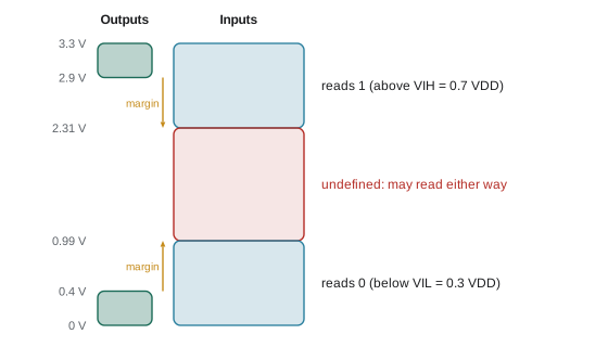
For CMOS devices, input thresholds are often specified as fractions of the supply: VIH at 0.7 × VDD and VIL at 0.3 × VDD. For a 3.3 V device that is 2.31 V and 0.99 V. Older 5 V TTL-compatible inputs use fixed thresholds of 2.0 V and 0.8 V, which is why a 3.3 V output can usually drive a 5 V TTL-compatible input directly. The reverse is not true: a 5 V output into a 3.3 V input exceeds the input's absolute maximum rating, typically VDD + 0.3 V, unless the input is specifically 5 V tolerant. Exceeding it forces current through the protection diodes and can latch up or slowly damage the chip.
Worked problem
Can these chips talk directly?
A 5 V Arduino-style board must read a signal from a 3.3 V sensor, and must send a signal to it. The 5 V board's input has VIH = 0.6 × VDD. The sensor's inputs are not 5 V tolerant.
Show solution
- Sensor to board: VIH = \( 0.6 \times 5 = 3.0 \) V. The sensor\'s high output is at most 3.3 V and, under load, perhaps 3.1 V. That leaves only about 0.1 V of margin, unreliable.
- Board to sensor: a 5 V high exceeds the sensor's absolute maximum of about 3.6 V, so it may damage the sensor.
- Both directions need level shifting.
Answer: Use a level shifter. For slow one-way signals a resistor divider works from 5 V down; for bidirectional buses such as I2C use a MOSFET-based shifter or a dedicated translator chip.
Level shifting
Robots mix logic voltages constantly: a 3.3 V microcontroller with 5 V servos, a 1.8 V camera sensor, a 5 V motor controller. Several techniques connect them. A two-resistor divider steps a one-way, low-speed 5 V signal down to 3.3 V. A single N-channel MOSFET with pull-up resistors on both sides makes a cheap bidirectional shifter suited to open-drain buses such as I2C, the classic circuit found on many breakout boards. Dedicated translator chips handle fast push-pull signals such as SPI, some automatically sensing direction. And a 3.3 V output driving a 5 V CMOS input that needs 3.5 V can use a buffer powered from 5 V with TTL-compatible inputs, such as the 74HCT family.
Real signals: rise time, ringing and noise
A real digital edge takes time to change. Rise time is usually defined as the time from 10 % to 90 % of the swing. Fast edges are good for speed but contain high-frequency energy that radiates and couples into neighbouring wires; slow edges are quieter but limit the data rate and spend longer in the undefined region, where noise can cause multiple transitions. When an output drives a capacitive load C through a resistance R, the signal follows an exponential with time constant τ = RC, and the 10 to 90 % rise time is:
This formula returns in lesson 9, where it limits how fast an I2C bus with pull-up resistors can run. Long wires add inductance as well as capacitance, and a fast edge on a long wire can overshoot and ring, briefly exceeding the supply or dipping below ground. Wires longer than about one-sixth of the distance the edge travels during its rise time behave as transmission lines and need termination, which is why CAN and RS-485 buses have 120 Ω resistors at each end, as lesson 10 explains.
Noise reaches digital lines from motor drivers, switching regulators, radio transmitters and electrostatic discharge. Defences include keeping signal wires short and away from motor wiring, twisting each signal with its ground return, using Schmitt-trigger inputs that have hysteresis, so the switching threshold is higher on a rising edge than on a falling one and small noise cannot cause chatter, and choosing differential signalling such as CAN for longer runs. Most microcontroller inputs have a Schmitt trigger option, and lesson 6 uses it for buttons and switches.
import math
def rise_time(r_ohm, c_farad):
    return 2.2 * r_ohm * c_farad

for r, c in [(50, 20e-12), (1_000, 100e-12), (4_700, 200e-12), (10_000, 400e-12)]:
    tr = rise_time(r, c)
    print(f"R = {r:6d} ohm, C = {c*1e12:4.0f} pF -> tr = {tr*1e9:8.1f} ns")
print(f"ln 9 = {math.log(9):.3f}")R = 50 ohm, C = 20 pF -> tr = 2.2 ns R = 1000 ohm, C = 100 pF -> tr = 220.0 ns R = 4700 ohm, C = 200 pF -> tr = 2068.0 ns R = 10000 ohm, C = 400 pF -> tr = 8800.0 ns ln 9 = 2.197
Common mistakes
MistakeCombining two sensor bytes as an unsigned number when the value is signed.
InsteadCheck the datasheet; apply two's complement conversion for signed fields.
MistakeWriting a whole register value to change one bit.
InsteadUse read-modify-write with masks, or the device's set and clear registers.
MistakeConnecting a 5 V output to a 3.3 V input that is not 5 V tolerant.
InsteadUse a level shifter or divider; check absolute maximum ratings.
MistakeAssuming a 3.3 V output always drives a 5 V input.
InsteadIt works for TTL-compatible inputs (VIH = 2.0 V) but not for CMOS inputs needing 0.7 × 5 V = 3.5 V.
MistakeRunning fast digital signals over long unshielded wires beside motor cables.
InsteadShorten, twist with ground, slow the edges, or switch to a differential bus.
Summary and key terms
- Binary uses base 2; each hexadecimal digit is four bits, so a byte is two hex digits.
- Signed values use two's complement; decode multi-byte sensor readings carefully.
- AND, OR, NOT, XOR and NAND gates implement Boolean logic; active-low signals are true when low.
- Bitwise OR sets, AND with an inverted mask clears, XOR toggles and AND tests register bits.
- Inputs read 1 above VIH and 0 below VIL; noise margin is the gap between output guarantees and input requirements.
- 5 V outputs can damage 3.3 V inputs; use dividers, MOSFET shifters or translator chips.
- Real edges have finite rise times (2.2RC), can ring on long wires and pick up noise; Schmitt triggers and good wiring help.
- Bit
- A binary digit, 0 or 1.
- Hexadecimal
- Base-16 notation in which each digit represents four bits.
- Two's complement
- The standard representation of signed integers, in which the top bit has negative weight.
- Register
- A memory location whose bits control or report the state of hardware.
- Mask
- A bit pattern used with bitwise operators to select, set or clear particular bits.
- Active-low
- A signal that is asserted, meaning true, when it is at the low voltage level.
- VIH and VIL
- The minimum input voltage guaranteed to read as high and the maximum guaranteed to read as low.
- Noise margin
- The difference between an output's guaranteed level and the next input's threshold.
- Level shifter
- A circuit that translates signals between different logic voltages.
- Schmitt trigger
- An input with hysteresis, having different thresholds for rising and falling signals.
Practice problems
Work each problem on paper first, then reveal the answer to check.
Convert 0x3C to decimal and binary.
Show answer
60 and 0011 1100.
What is the 8-bit two's complement pattern for −5?
Show answer
1111 1011 (0xFB).
Which bitwise operation clears bit 3 of reg?
Show answer
reg &= ~(1 << 3).
A register reads 0b1010_0110. What is the value of the 2-bit field at bits 1 and 2?
Show answer
(0b10100110 >> 1) & 0b11 = 0b11 = 3.
For a 3.3 V CMOS input with VIH = 0.7 VDD, what voltage guarantees a 1?
Show answer
At least 2.31 V.
Why can a 3.3 V output usually drive a 74HCT input powered at 5 V?
Show answer
HCT inputs have TTL-compatible thresholds with VIH = 2.0 V.
A 10 kΩ pull-up drives 300 pF. Estimate the rise time.
Show answer
2.2 × 10,000 × 300 × 10⁻¹² = 6.6 µs.
By De Morgan, NOT (A OR B) equals what?
Show answer
(NOT A) AND (NOT B).
A motor may run only if software enable is 1, e-stop is closed (1) and the watchdog is alive (1). Which gate combines them?
Show answer
A three-input AND.
What does hysteresis in a Schmitt trigger prevent?
Show answer
Multiple false transitions when a slow or noisy signal crosses the threshold.
Lesson quiz · 5 questions
Score 60% or more to complete this lesson.
Create a free account to save your progress, take quizzes and earn a certificate.