
ROB-100 · Lesson 4 of 12 · 28 min
Describing position and motion
Before a robot can reach for a cup, drive to a charging dock or avoid a pedestrian, it needs a precise way to describe where things are and how they are moving. Where is the robot? Where is its gripper? Where is the cup, as seen by the camera, and where is it relative to the gripper? These questions are answered with coordinate frames, positions, orientations and the transformations that convert between frames. This lesson introduces those ideas gently, using algebra and a little trigonometry. It covers coordinate frames and why robots use many of them, position and orientation together as a pose, rotating and translating points in two dimensions, chaining transformations from one frame to another, the idea of a robot's workspace, and how velocity and acceleration describe motion. These are the foundations for the kinematics course later in the program, where the same ideas are extended to three dimensions with matrices.
Coordinate frames
A coordinate frame is a reference from which positions and directions are measured. It has an origin, a point where all coordinates are zero, and a set of perpendicular axes, usually called x, y and z. On a flat floor, two axes are enough: x and y. Robots use many frames at once, because different things are naturally described from different points of view. A world frame, sometimes called a map frame, is fixed to the environment, such as one corner of a warehouse. A robot base frame moves with the robot, often with x pointing forward, y to the left and z up, a convention ROS uses. Each sensor has its own frame: a camera measures objects relative to itself, and a lidar measures distances from its own centre. A robot arm has a frame for each link and a tool frame at the gripper. An object to be picked up may have its own frame too.
Using many frames makes each measurement simple in its own frame, but it means the robot must constantly convert coordinates from one frame to another. A camera may see a cup 0.5 m in front of itself; to grasp it, the robot needs to know where the cup is relative to its base, which depends on where the camera is mounted, and the planner needs to know where it is on the map, which depends on where the robot is. Keeping track of all these relationships correctly is one of the most common sources of bugs in robot software, and ROS includes a dedicated system, called tf2, for managing frames and their transformations over time.
Position, orientation and pose
The position of a point in a frame is given by its coordinates, such as \( (x, y) \) on a plane or \( (x, y, z) \) in space. But a robot or object is not just a point: it also faces a direction. Its orientation describes which way it is turned. On a plane, orientation is a single angle, often written \( \theta \) and called the heading or yaw, usually measured counter-clockwise from the frame's x axis. In three dimensions, orientation needs three numbers, such as roll, pitch and yaw angles, or other representations such as rotation matrices and quaternions that avoid some of the pitfalls of angles. Position and orientation together are called a pose. A mobile robot on a floor has a pose \( (x, y, \theta) \); a gripper in space has a six-number pose, three for position and three for orientation, matching the six degrees of freedom of lesson 3.
Angles cause a surprising number of errors. Robots and software libraries usually measure angles in radians, not degrees: a full turn is \( 2\pi \) radians, about 6.283, so 90° is \( \pi/2 \), about 1.571 radians. Mixing the two is a classic mistake. Headings also wrap around: a heading of 359° is only 2° away from 1°, not 358°, so software that compares headings must handle the wrap. Conventions differ too, such as whether positive angles are counter-clockwise or clockwise, and whether z points up or down, as it often does in aircraft. Good practice is to state units and conventions explicitly and stick to them throughout a project.
Rotating a point in two dimensions
Suppose a point has coordinates \( (x, y) \) in a frame, and we rotate it counter-clockwise about the origin by an angle \( \theta \). The new coordinates \( (x', y') \) are given by the rotation equations, which come straight from trigonometry:
For example, rotating the point \( (1, 0) \) by 90° gives \( (\cos 90^\circ, \sin 90^\circ) = (0, 1) \): a point on the x axis moves onto the y axis. The same equations convert coordinates between two frames that share an origin but are turned relative to each other. If a robot is turned by \( \theta \) relative to the world, a point measured as \( (x, y) \) in the robot's frame has world coordinates found by rotating by \( \theta \). In the kinematics course you will write these equations as a 2-by-2 rotation matrix, which makes chains of rotations easy to compute.
Adding translation: from one frame to another
Frames usually differ by both a rotation and a translation, a shift of the origin. If a robot stands at position \( (x_r, y_r) \) in the world with heading \( \theta \), a point measured at \( (x_p, y_p) \) in the robot's frame has world coordinates found by rotating it by \( \theta \) and then adding the robot's position:
This combination of rotation and translation is called a rigid transformation, because it moves things without stretching or bending them: distances and angles are preserved. It is the single most used calculation in robotics.
Worked problem
Where is the obstacle on the map?
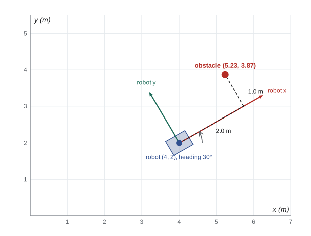
A robot stands at (4.0 m, 2.0 m) in the world frame with a heading of 30°. Its lidar, mounted at the robot's centre, detects an obstacle 2.0 m directly ahead and 1.0 m to the left, that is, at (2.0, 1.0) in the robot frame. Where is the obstacle in the world frame?
Show solution
- \( \cos 30^\circ \approx 0.866 \) and \( \sin 30^\circ = 0.5 \).
- Rotate: \( x = 2.0 \times 0.866 - 1.0 \times 0.5 = 1.232 \); \( y = 2.0 \times 0.5 + 1.0 \times 0.866 = 1.866 \).
- Translate: \( x_w = 4.0 + 1.232 = 5.232 \); \( y_w = 2.0 + 1.866 = 3.866 \).
- Check: the distance from the robot is still about 2.24 m, the same as in the robot frame, as a rigid transformation requires.
Answer: About (5.23 m, 3.87 m) in the world frame.
Chaining transformations
Real robots chain several transformations. To find where a cup seen by a camera is on the map, the robot combines the transformation from the camera to the robot base, which is fixed by how the camera is mounted and found by calibration, with the transformation from the robot base to the world, which changes as the robot moves and is estimated by localization. Going the other way, from world to camera, uses the inverse transformations. For a robot arm, the chain runs from the base through each joint and link to the tool, and each joint angle changes one link of the chain. Working out the position of the tool from the joint angles in this way is called forward kinematics; working out the joint angles needed to put the tool at a desired pose is called inverse kinematics, and it is usually much harder, sometimes with several solutions or none.
Worked problem
Forward kinematics of a two-link arm
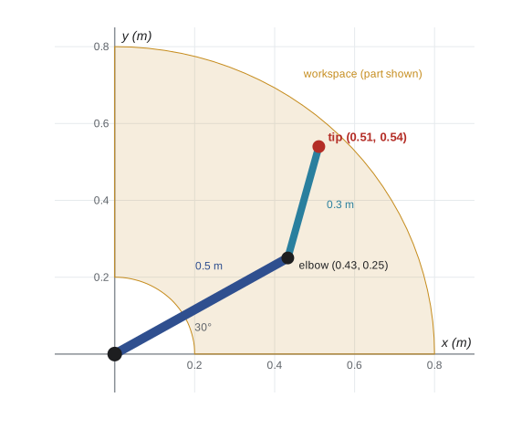
A planar arm has two links, 0.5 m and 0.3 m long. The first joint, at the origin, is at 30° from the x axis, and the second joint is bent a further 45°. Where is the tip of the arm?
Show solution
- Elbow position: \( (0.5\cos 30^\circ, 0.5\sin 30^\circ) = (0.433, 0.250) \).
- The second link points at \( 30^\circ + 45^\circ = 75^\circ \).
- Tip offset: \( (0.3\cos 75^\circ, 0.3\sin 75^\circ) \approx (0.078, 0.290) \).
- Tip: \( (0.433 + 0.078, 0.250 + 0.290) = (0.511, 0.540) \) m.
Answer: About (0.51 m, 0.54 m) from the base.
The workspace
A robot's workspace is the set of positions its tool can reach. For the two-link arm in the example, if both joints can turn freely, the tip can reach any point between an inner radius of 0.5 − 0.3 = 0.2 m and an outer radius of 0.5 + 0.3 = 0.8 m, forming a ring. Real arms have joint limits, so their workspaces are more complicated shapes, and points near the edges can often be reached only in some orientations. Robot manufacturers publish workspace diagrams and the reach of each model. When designing a robot cell, engineers check that every point the robot needs to reach lies comfortably inside the workspace and that the full space the robot can sweep, including its links, is guarded or otherwise made safe. For a mobile robot, the equivalent question is which areas it can drive to, given its size, turning ability and the obstacles around it.
Velocity and acceleration
Motion is change of position over time. Velocity is the rate of change of position and has both a speed and a direction; for a robot moving in a plane it has an x component and a y component, plus an angular velocity, the rate of change of heading, usually written \( \omega \) and measured in radians per second. Acceleration is the rate of change of velocity. Robots care about acceleration because forces are needed to change velocity, as Newton's second law, \( F = ma \), states: a robot that accelerates too hard may slip its wheels, tip over, spill its load or exceed its motor limits. Smooth motion is therefore planned with limits on velocity, acceleration and sometimes jerk, the rate of change of acceleration.
For motion in a straight line with constant acceleration, the familiar equations of motion apply: the speed after time \( t \) is \( v = v_0 + at \), and the distance travelled is \( d = v_0 t + \tfrac{1}{2}at^2 \). A related idea is the stopping distance, which is central to robot safety: a robot travelling at speed \( v \) that brakes with deceleration \( a \) needs a distance of \( v^2 / 2a \) to stop, plus whatever it travels during the time it takes to detect a hazard and react.
Worked problem
Stopping distance of a mobile robot
A warehouse robot travels at 2.0 m/s. Its safety system takes 0.1 s to detect an obstacle and command braking, and it can then decelerate at 1.0 m/s². How far does it travel before stopping?
Show solution
- Reaction distance: \( 2.0 \times 0.1 = 0.2 \) m.
- Braking distance: \( v^2 / 2a = 2.0^2 / (2 \times 1.0) = 2.0 \) m.
- Total: \( 0.2 + 2.0 = 2.2 \) m.
Answer: 2.2 m, so its sensors must detect obstacles well beyond that distance.
| Quantity | Symbol | Units | Robotics example |
|---|---|---|---|
| Position | x, y, z | m | Where the gripper is |
| Orientation | θ, or roll, pitch and yaw | rad or ° | Which way the robot faces |
| Pose | (x, y, θ) or 6 numbers | m and rad | A robot's full placement |
| Velocity | v | m/s | Driving speed |
| Angular velocity | ω | rad/s | Turning rate |
| Acceleration | a | m/s² | How quickly speed changes |
Common mistakes
MistakeMixing degrees and radians.
InsteadUse radians in software and convert explicitly when displaying degrees.
MistakeForgetting which frame a measurement is in.
InsteadLabel every coordinate with its frame and transform explicitly.
MistakeTranslating before rotating when converting from robot to world frame.
InsteadRotate the point by the heading first, then add the robot's position.
MistakeComparing headings without handling wrap-around.
InsteadWrap angle differences into a range such as −180° to 180°.
MistakePlanning motion with no acceleration limits.
InsteadLimit acceleration and allow for reaction and braking distance.
Summary and key terms
- Coordinate frames have an origin and axes; robots use world, base, sensor, tool and object frames.
- A pose combines position and orientation: (x, y, θ) on a plane, six numbers in space.
- Rotation by θ follows x' = x cos θ − y sin θ and y' = x sin θ + y cos θ.
- A rigid transformation rotates and then translates, preserving distances and angles.
- Chaining transformations links sensors, robots, arms and maps; forward kinematics follows the chain.
- The workspace is the set of positions a robot's tool can reach.
- Velocity, acceleration and stopping distance govern how robots move safely.
- Coordinate frame
- An origin and axes from which positions are measured.
- World frame
- A frame fixed to the environment.
- Pose
- Position and orientation together.
- Heading
- The angle a mobile robot faces in the plane.
- Radian
- The standard unit of angle; 2π radians make a full turn.
- Rigid transformation
- A rotation and translation that preserves distances.
- Forward kinematics
- Finding the tool pose from the joint angles.
- Inverse kinematics
- Finding joint angles that achieve a desired tool pose.
- Workspace
- The region a robot's tool can reach.
- Angular velocity
- The rate of change of orientation.
Practice problems
Work each problem on paper first, then reveal the answer to check.
Convert 90° to radians.
Show answer
π/2, about 1.571 rad.
Rotate (1, 0) by 90° counter-clockwise.
Show answer
(0, 1).
Rotate (0, 2) by 90° counter-clockwise.
Show answer
(−2, 0).
A robot at (1, 1) with heading 0° sees a point at (2, 0). World coordinates?
Show answer
(3, 1).
A robot at (0, 0) with heading 90° sees a point at (1, 0). World coordinates?
Show answer
(0, 1).
Outer reach of an arm with 0.4 m and 0.25 m links?
Show answer
0.65 m.
What is inverse kinematics?
Show answer
Finding joint angles that place the tool at a desired pose.
Braking distance at 1 m/s with 0.5 m/s² deceleration?
Show answer
1 m.
Why are radians preferred in software?
Show answer
Trigonometric functions in most libraries use radians.
What ROS system manages frames?
Show answer
tf2.
Lesson quiz · 5 questions
Score 60% or more to complete this lesson.
Create a free account to save your progress, take quizzes and earn a certificate.