
ROB-100 · Lesson 3 of 12 · 28 min
Robot anatomy: bodies, sensors, actuators and computers
Open up almost any robot and you will find the same basic parts, arranged in different ways. There is a mechanical structure that holds everything together and gives the robot its shape; joints and links that let parts of it move; actuators that produce motion; a drive train that transmits and adapts that motion; sensors that measure the robot and its surroundings; a computer, or several, that runs the robot's software; a power system that supplies energy; communication links; and, at the business end, tools or end effectors that interact with the world. This lesson walks through each subsystem, explains what it does and how it is usually built, introduces the important idea of degrees of freedom, and shows how designers balance the trade-offs between them. Later lessons look more closely at sensing, motion and control; here the aim is a map of the whole machine.
The mechanical structure: links, joints and frames
A robot's body is built from rigid parts called links, connected by joints that allow relative motion. In a robot arm, the links are the segments of the arm, and the joints are like a shoulder, an elbow and a wrist. In a mobile robot, the structure is a chassis or frame that carries the wheels, battery, computer and sensors. Structures are usually made of aluminum, steel, engineering plastics or carbon-fibre composites, chosen for stiffness, strength, weight and cost. Stiffness matters more than many beginners expect: a flexible arm bends under load and vibrates when it moves quickly, so its tool ends up somewhere other than where the software thinks it is. Weight matters too, because every gram the robot carries must be accelerated by its motors and powered by its battery.
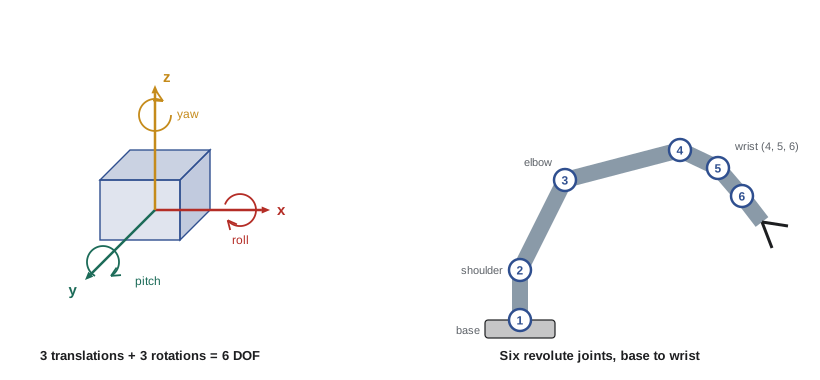
Robot joints come in two basic types. A revolute joint rotates about an axis, like a hinge or an elbow; a prismatic joint slides along an axis, like a drawer or a telescope. Most robot arms use revolute joints because they are compact and can reach a large workspace, while gantry robots, which move a tool over a rectangular area along rails, use prismatic joints. Other joint types, such as spherical joints that rotate in all directions, can be built by combining simpler ones.
Degrees of freedom
The number of independent ways a robot or a part of it can move is called its degrees of freedom (DOF). A rigid object floating freely in space has six degrees of freedom: it can move along three directions, usually called x, y and z, and it can rotate about three axes, often called roll, pitch and yaw. To place a tool at any position in any orientation within its reach, a robot arm therefore needs at least six joints, which is why six-axis arms are the most common industrial robots. An arm with fewer joints can still be very useful for tasks that need fewer freedoms: a four-axis SCARA arm moves in a plane, raises and lowers its tool, and rotates it about a vertical axis, which is ideal for placing parts on a circuit board. An arm with more than six joints, such as a seven-axis arm, is called redundant: it can reach the same tool pose in many ways, which helps it avoid obstacles, much as you can move your elbow while keeping your hand still on a table.
A wheeled robot on a flat floor has three degrees of freedom in the plane: position along x and y, and heading. But a typical robot with two driven wheels cannot move sideways directly, so it controls only two of those freedoms at any instant, forward speed and turning rate, and must manoeuvre to reach a sideways position, as a car must when parallel parking. Lesson 6 explores this difference between the freedoms a robot has and the ones it can control directly.
Worked problem
Counting degrees of freedom
A robot consists of a wheeled base that moves on a flat floor with full control of x, y and heading, carrying a four-joint arm with revolute joints. How many degrees of freedom does the whole system have, and is it redundant for placing a tool in six degrees of freedom?
Show solution
- Base on a plane: 3 DOF (x, y and heading).
- Arm: 4 revolute joints, 4 DOF.
- Total: 3 + 4 = 7 DOF.
- Seven exceeds the six needed for a full tool pose, so the system is redundant in principle, though not every combination of base and arm motion can produce every pose: the arm's reach and joint layout still limit what is possible.
Answer: 7 DOF; redundant on paper, with real limits set by reach and geometry.
Actuators: the robot's muscles
Actuators convert energy into motion. Most robots use electric motors, because electricity is easy to store, switch and control precisely. Brushed DC motors are cheap and simple and common in hobby and educational robots. Brushless DC motors, controlled electronically, are more efficient and longer-lasting and drive most drones, many mobile robots and most modern robot arms. Stepper motors move in small fixed steps and can position things accurately without a sensor, which makes them popular in 3-D printers and small machines, though they can lose steps if overloaded. Servo motors, in the robotics sense, combine a motor with a position sensor and a controller so they can be commanded to an angle; hobby servos do this in a small, cheap package, while industrial servo drives do it with great precision and power.
Other actuators fill special niches. Hydraulic actuators use pressurized oil to produce very large forces in a compact package and are used in heavy machinery, some legged robots and construction equipment. Pneumatic actuators use compressed air; they are fast, cheap and naturally compliant, and pneumatic grippers and suction cups are everywhere in factories. Soft actuators, made of flexible materials driven by air, fluid or electrical effects, are an active research area for robots that must handle delicate objects or work safely against people.
Drive trains: gears, belts and screws
Electric motors generally spin fast with little torque, while robot joints and wheels usually need to turn slowly with a lot of torque. A drive train, also called a transmission, sits between them. Gearboxes trade speed for torque: a gear ratio of 50 to 1 makes the output turn 50 times more slowly than the motor but with up to 50 times the torque, less losses to friction. Robot arms often use compact, high-ratio gearboxes such as harmonic drives, also called strain wave gears, and cycloidal drives, which have very little backlash, the small free play between gear teeth that makes positioning less precise. Belts and pulleys transmit motion over a distance quietly, and lead screws and ball screws turn rotation into precise straight-line motion. Some modern legged robots and collaborative arms use motors with low gear ratios, sometimes called quasi-direct drives, so the joint can sense and respond to forces quickly. Lesson 6 includes a worked example of gear-ratio calculations.
Sensors: proprioceptive and exteroceptive
Sensors fall into two broad families. Proprioceptive sensors measure the robot's own state: encoders measure the angle or rotation of joints and wheels; current sensors in the motor drives estimate the torque the motors produce; inertial measurement units (IMUs), combining accelerometers and gyroscopes, measure acceleration and rotation rate; and battery monitors track voltage and charge. Exteroceptive sensors measure the outside world: cameras, depth cameras, lidar, radar, ultrasonic range sensors, bump switches, microphones, force and tactile sensors, and satellite positioning receivers. Some sensors straddle the two, such as a force-torque sensor at a robot's wrist, which measures the forces between the robot and whatever it touches. Lesson 5 explains how the main sensors work and how to judge their range, resolution and accuracy.
Computers and electronics
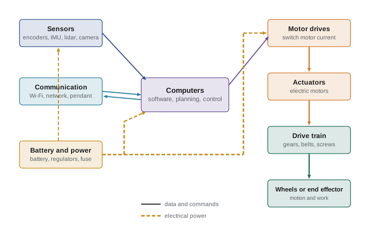
The robot's brain is rarely a single computer. Most robots have a layered set of processors. At the bottom, microcontrollers, small, cheap computers on a single chip, run fast, time-critical loops: reading encoders, switching motor drives and checking safety signals thousands of times a second. Motor drives themselves contain their own processors. Above them, one or more single-board computers or industrial PCs run the main robot software, often on Linux with ROS 2, handling navigation, planning and communication. Robots that process camera images with machine learning often carry a graphics processing unit (GPU) or a dedicated AI accelerator. Industrial robots have a robot controller, a cabinet containing the computers and drives, and a teach pendant, a handheld unit used to program and jog the robot. Separate safety controllers or safety-rated programmable logic controllers (PLCs) often monitor emergency stops and guards independently of the main software, so a software crash cannot disable them. The different processors communicate over buses and networks such as CAN, EtherCAT and Ethernet.
Power and energy
Fixed industrial robots are usually connected to mains electricity, often three-phase power. Mobile robots carry their energy with them, almost always in rechargeable lithium-ion batteries, and energy is one of the hardest constraints in mobile robot design. Battery capacity is often quoted in ampere-hours (Ah) at a nominal voltage, and the energy stored is the product of the two, in watt-hours (Wh). Runtime depends on how much power the robot draws on average: motors, computers and sensors all consume energy, and motors draw much more when climbing, accelerating or carrying loads. Designers also plan for the fact that batteries should not be fully drained, that their capacity fades with age and cold, and that lithium-ion cells need protection circuits to prevent overheating and fire. Many mobile robots return to a charging dock on their own when their battery runs low, and some warehouse robots swap batteries automatically.
Here \( E \) is the stored energy in watt-hours, \( V \) the nominal voltage, \( C \) the capacity in ampere-hours, \( u \) the usable fraction of the capacity and \( P_{\text{avg}} \) the average power draw in watts. The runtime \( t \) comes out in hours.
Worked problem
Estimating battery runtime
A small mobile robot has a 24 V, 20 Ah lithium-ion battery. Its motors average 90 W while driving, its computer 25 W and its sensors 15 W. The designers use only 80 % of the battery's capacity to protect the cells. Estimate its driving runtime.
Show solution
- Stored energy: \( E = 24 \times 20 = 480 \) Wh.
- Usable energy: \( 480 \times 0.8 = 384 \) Wh.
- Average power: \( 90 + 25 + 15 = 130 \) W.
- Runtime: \( t = 384 / 130 \approx 2.95 \) h.
- In cold weather, with a heavy load, or as the battery ages, the real runtime will be shorter, so designers add a margin.
Answer: About 3 hours of driving, less in cold conditions or with an older battery.
End effectors and communication
The end effector is the part of the robot that actually does the work: a gripper, a suction cup, a welding torch, a paint gun, a screwdriver, a camera or a surgical instrument. Grippers range from simple two-finger parallel grippers to vacuum grippers that lift boxes with suction, soft grippers that wrap around fruit, and multi-fingered robot hands. Industrial robots often use tool changers so one arm can switch between tools. Robots also communicate: with operators through screens, pendants and apps; with other machines through industrial networks; and with remote servers and other robots through Wi-Fi, cellular networks or, in space, radio links with long delays. Reliable, secure communication has become part of robot design, because a robot that can be taken over remotely can cause physical harm.
| Subsystem | Purpose | Common examples |
|---|---|---|
| Structure | Holds parts, sets shape and stiffness | Aluminium frames, cast arms, composite links |
| Joints | Allow relative motion | Revolute and prismatic joints |
| Actuators | Produce motion and force | Brushless motors, steppers, hydraulics, pneumatics |
| Drive train | Adapts speed and torque | Gearboxes, harmonic drives, belts, ball screws |
| Sensors | Measure robot and world | Encoders, IMUs, cameras, lidar, force sensors |
| Computers | Run control and software | Microcontrollers, single-board computers, robot controllers |
| Power | Supplies energy | Lithium-ion batteries, mains power |
| End effector | Interacts with objects | Grippers, suction cups, torches, tools |
Common mistakes
MistakeIgnoring stiffness and weight when choosing a structure.
InsteadRemember that flexible, heavy structures reduce accuracy and runtime.
MistakeAssuming a robot needs many joints for every task.
InsteadMatch the degrees of freedom to the task, such as a SCARA arm for planar assembly.
MistakeConnecting a fast motor directly to a heavy load.
InsteadUse a drive train to trade speed for torque.
MistakeCalculating runtime from full battery capacity at ideal conditions.
InsteadUse usable capacity, realistic average power and a margin.
MistakeRelying on the main software for emergency stops.
InsteadUse independent, safety-rated circuits for safety functions.
Summary and key terms
- Robots are built from links and joints driven by actuators through drive trains.
- Revolute joints rotate and prismatic joints slide.
- A free rigid body has six degrees of freedom; six-axis arms can reach any pose within their workspace.
- Electric motors are the most common actuators; hydraulics and pneumatics fill niches.
- Proprioceptive sensors measure the robot; exteroceptive sensors measure the world.
- Robots use layered computers, from microcontrollers to robot controllers and GPUs.
- Battery energy, usable capacity and average power set a mobile robot's runtime.
- Link
- A rigid part of a robot's structure.
- Revolute joint
- A joint that rotates about an axis.
- Prismatic joint
- A joint that slides along an axis.
- Degrees of freedom
- The number of independent ways a body or robot can move.
- Redundant robot
- A robot with more degrees of freedom than its task needs.
- Brushless DC motor
- An efficient, electronically commutated electric motor.
- Backlash
- Free play between gear teeth that reduces precision.
- Proprioceptive sensor
- A sensor that measures the robot's own state.
- Exteroceptive sensor
- A sensor that measures the environment.
- End effector
- The tool at the end of a robot that interacts with objects.
Practice problems
Work each problem on paper first, then reveal the answer to check.
What is the difference between a link and a joint?
Show answer
Links are rigid parts; joints let them move relative to each other.
How many degrees of freedom does a free rigid body have?
Show answer
Six: three translations and three rotations.
Why are six-axis arms common?
Show answer
Six joints let the tool reach any position and orientation in the workspace.
What makes a robot redundant?
Show answer
Having more degrees of freedom than the task requires.
Name two kinds of electric motor used in robots.
Show answer
Brushed DC, brushless DC, stepper, servo.
Why do robots use gearboxes?
Show answer
To trade motor speed for joint or wheel torque.
Give one proprioceptive and one exteroceptive sensor.
Show answer
Encoder or IMU; camera or lidar.
What is a teach pendant?
Show answer
A handheld unit for programming and jogging an industrial robot.
Energy in a 48 V, 10 Ah battery?
Show answer
480 Wh.
Runtime of 300 Wh usable at 100 W average?
Show answer
3 hours.
Lesson quiz · 5 questions
Score 60% or more to complete this lesson.
Create a free account to save your progress, take quizzes and earn a certificate.