
RAC-330 · Lesson 9 of 12 · 17 min
Duct design and sizing
The Novaks had one more project for the spring: the basement. It had been finished in the 1990s with a recreation room, an office and a small bathroom, all fed by short flexible ducts teed off the main trunk wherever they happened to reach, and the recreation room was always the coldest room in the house. Irene wanted it done properly while the ceiling was open for new lighting. Dana gave the design to Theo, with Marcus to check it. "You did the loads," she said. "Now give each room its air."
This lesson explains how residential and light commercial ducts are sized: room airflows from the loads, the pressure available for the ducts, equivalent lengths, the equal friction method, velocity limits, duct materials, and duct sealing and leakage testing. It works through the Novak basement and the second return from lesson 7.
From loads to room airflows
Duct design starts from the room-by-room loads of lessons 5 and 6. Each room's share of the system airflow is its share of the load: a room with 15 % of the house's heating load gets 15 % of the heating airflow. Where heating and cooling shares differ, as they do for a sunny room with a lot of west glass or a basement room that needs heat but little cooling, the designer takes the larger requirement or balances the two, and may provide dampers so the household can adjust between seasons.
For the Novak house, the system airflow was 539 L/s, set by the heat pump in lesson 12 of RAC-320. The basement rooms' heating loads gave the recreation room about 110 L/s, the office 50 L/s and the bathroom 24 L/s. The recreation room's 110 L/s would come from two outlets of 55 L/s each, so the warm air reached both ends of the room.
The pressure available for ducts
The blower can provide only so much pressure, and the ducts get what is left after the other components. Manual D, the ACCA residential duct design method, and the comparable Canadian practice in HRAI's residential design courses, start from the blower's rated external static pressure at the design airflow and subtract the pressure drops of everything outside the cabinet that is not duct: the filter, any external coil, supply registers, return grilles, balancing dampers and accessories such as humidifiers or zoning dampers. What remains is divided between the supply and return sides, usually with somewhat more for the supply.
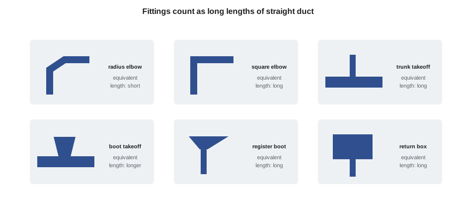
That available pressure is spread over the longest run on each side. Because fittings cause far more loss than straight duct, each fitting is given an equivalent length: the length of straight duct that would cause the same loss. A sharp elbow, a boot or a takeoff from a trunk can be equivalent to several metres to 10 m or more of duct. The total effective length of a run is its straight length plus the equivalent lengths of all its fittings. The design friction rate is the available pressure divided by the longest total effective length, so that the longest run, which has the most resistance, still gets its air.
\text{friction rate} = \frac{\text{available static pressure}}{\text{longest total effective length}} \quad \text{Pa/m}
The equal friction method
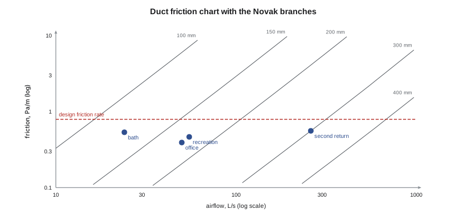
In the equal friction method, every section of duct is sized so that it loses about the same pressure per unit length, the design friction rate. A duct friction chart or calculator gives, for each airflow and friction rate, the round duct diameter and the air velocity. The designer picks the next larger standard size, and converts round sizes to equivalent rectangular sizes where a rectangular duct is needed to fit between joists. Shorter runs, which need less of the available pressure, end up with more pressure than they need and are trimmed with balancing dampers.
The friction itself comes from the Darcy equation and a friction factor that depends on the duct's roughness and the Reynolds number of the flow. Charts are drawn for galvanized steel; flexible duct has much more friction, especially when it is not stretched straight, and lined or rough ducts somewhat more. The script uses the Altshul–Tsal friction factor, a simple form that agrees well with the charts.
Velocity is checked as well. High velocities make noise at registers and in the ducts near bedrooms; typical residential guidance keeps supply branches below about 3 m/s (600 fpm) and trunks below about 4.5 m/s (900 fpm), with return grilles and returns lower still, because return grilles are often in living spaces and their noise is noticed.
The Novak basement
Theo started with the blower's rated external static and subtracted the filter, the registers and the return grille. He found the longest supply run, from the air handler to the far end of the recreation room, and the longest return run, and added up their straight lengths and fittings. The script divides the available pressure into supply and return friction rates, sizes the basement branches to the supply rate, and sizes the second return, from lesson 7, to the return rate.
import math
RHO, NU, EPS = 1.2, 1.5e-5, 0.00009            # air density kg/m3, kinematic viscosity m2/s, galvanized roughness m
def friction_pa_per_m(q_ls, d_m):
    """Pressure loss per metre of round duct (Altshul-Tsal friction factor)."""
    a = math.pi * d_m ** 2 / 4
    v = q_ls / 1000 / a
    re = v * d_m / NU
    f = 0.11 * (EPS / d_m + 68 / re) ** 0.25
    f = f if f >= 0.018 else 0.85 * f + 0.0028
    return f / d_m * RHO * v ** 2 / 2, v
def size_round(q_ls, rate, sizes):
    """Smallest standard size whose friction is at or below the design rate."""
    for d in sizes:
        loss, v = friction_pa_per_m(q_ls, d)
        if loss <= rate:
            return d, loss, v
    return sizes[-1], *friction_pa_per_m(q_ls, sizes[-1])

rated, filt, regs, grille = 125, 25, 8, 8      # Pa: blower's rated external static and component losses
available = rated - filt - regs - grille
supply_share, return_share = 50, available - 50
tel_supply = 18 + 45                           # m: longest supply run, straight length + fitting equivalent lengths
tel_return = 9 + 30
fr_s, fr_r = supply_share / tel_supply, return_share / tel_return
print(f"available for ducts {available} Pa; friction rate supply {fr_s:.2f} Pa/m, return {fr_r:.2f} Pa/m")
SIZES = [0.100, 0.125, 0.150, 0.175, 0.200, 0.250, 0.300, 0.350, 0.400]
rooms = {"recreation room (each of 2)": 55, "basement office": 50, "basement bath": 24}
for name, q in rooms.items():
    d, loss, v = size_round(q, fr_s, SIZES)
    print(f"{name:28s} {q:4d} L/s -> {d * 1000:.0f} mm, {loss:.2f} Pa/m, {v:.1f} m/s")
d, loss, v = size_round(260, fr_r, SIZES)
print(f"{'second return':28s}  260 L/s -> {d * 1000:.0f} mm, {loss:.2f} Pa/m, {v:.1f} m/s")
l2, v2 = friction_pa_per_m(260, 0.200)
print(f"the same return in 200 mm would lose {l2:.2f} Pa/m at {v2:.1f} m/s")available for ducts 84 Pa; friction rate supply 0.79 Pa/m, return 0.87 Pa/m recreation room (each of 2) 55 L/s -> 175 mm, 0.46 Pa/m, 2.3 m/s basement office 50 L/s -> 175 mm, 0.39 Pa/m, 2.1 m/s basement bath 24 L/s -> 125 mm, 0.53 Pa/m, 2.0 m/s second return 260 L/s -> 300 mm, 0.56 Pa/m, 3.7 m/s the same return in 200 mm would lose 4.08 Pa/m at 8.3 m/s
The supply friction rate came to about 0.79 Pa/m. Each recreation room branch needed 175 mm round, the office 175 mm and the bathroom 125 mm, all at low velocities of about 2 m/s. The second return, carrying about 260 L/s from the far end of the house, needed 300 mm; in 200 mm, the size of the short flexible duct a previous owner had used for a basement return, it would have lost nearly five times the design rate at over 8 m/s, which explains both the high static pressure and the whistle Mrs. Novak used to hear from the basement.
Marcus checked Theo's work and made two changes. He moved the recreation room outlets from the ceiling at the inside wall to the ceiling near the exterior wall, aimed toward the room, so that the warm air would wash the cold basement wall, which lesson 10 explains. And he replaced the old tees off the trunk with proper takeoffs with balancing dampers, because a tee taken off the end of a trunk with a crushed flex duct had been costing the old recreation room most of its air.
Duct materials and installation
Galvanized steel is the standard material for trunks and most branches. Flexible duct is convenient for short connections but must be fully stretched, supported at short intervals and kept as straight as possible; compressed or sagging flex can have several times the friction of the chart value, and a single sharp kink can choke off a branch. Duct board and duct liner reduce noise and heat loss but add roughness. Ducts in unconditioned spaces, such as attics, crawlspaces and garages, must be insulated and sealed, and in cooling climates must have a vapour retarder on the insulation to prevent condensation.
All joints and seams should be sealed with mastic or listed tapes, not the cloth duct tape that dries and falls off. Leaks on the supply side lose conditioned air; leaks on the return side draw in air from wherever the ducts run, which in a basement with a combustion appliance can be dangerous, because a leaky return near a water heater or furnace can depressurize the space and pull flue gases back into the house.
Duct leakage testing
Duct leakage is measured with a calibrated fan, a duct tester, connected to the system with all registers and grilles sealed. The fan pressurizes the ducts to 25 Pa and its airflow at that pressure is the duct leakage. Two results are common: total leakage, to everywhere, and leakage to outdoors, measured with a blower door holding the house at the same pressure as the ducts, so that only leaks to outside the house show.
Energy codes and programs in Canada increasingly expect ducts to be sealed, and some energy efficiency programs and compliance paths in provincial codes require or credit tested duct leakage. Designers and installers should check what the current provincial code and any program the owner is using require.
Northfield ran a duct leakage test on the Novaks' system after the basement work. All the ducts were inside the conditioned envelope, so the leakage stayed in the house, but sealing the old trunk seams and the new takeoffs still mattered: leaks to the wrong room are lost from the room that needed them.
Common duct design shortcuts and why they fail
Marcus had seen many basements like the Novaks' and could list the shortcuts that produced them. The first was sizing every branch the same, 150 mm round to every room regardless of its load, which gives the nearest rooms far too much air and the farthest far too little. The second was taking branches off the end cap of a trunk, where the air arrives fast and straight and shoots past the takeoff, instead of off the side with a proper fitting. The third was running long, loose flexible duct to save fittings, which turns a short, cheap branch into a large hidden resistance. The fourth was forgetting the return entirely and relying on a single central grille for a whole house, which is what had starved the Novaks' blower. The last was skipping the balancing dampers, so that nothing could be adjusted afterwards.
None of these shortcuts saves much on the day. All of them cost the household for the life of the system, in comfort, noise and energy, and they are much harder to fix once a ceiling is closed. That was why Dana insisted on doing the basement while it was open.
Theo also learned to check his design against the equipment before ordering parts. The air handler's blower table gave the airflow at the design total external static pressure; the sum of the room airflows had to match it; and the pressure drops of the filter, registers and grilles had to come from the products actually being installed, not from typical values. A design that adds up on paper but uses a filter with twice the assumed resistance will not deliver its airflows.
Common mistakes
MistakeSizing ducts by rule of thumb or by the size of the outlet on the equipment.
InsteadSize from room airflows, available pressure and total effective length.
MistakeForgetting fittings when finding the longest run.
InsteadAdd equivalent lengths; fittings often exceed the straight length.
MistakeUsing flexible duct compressed and sagging.
InsteadStretch it fully, support it and keep it short and straight.
MistakeSealing ducts with cloth duct tape.
InsteadUse mastic or listed tapes.
MistakeIgnoring return leaks near combustion appliances.
InsteadSeal returns; depressurization can pull flue gases into the house.
Summary and key terms
- Room airflows come from the room-by-room loads.
- Available static pressure is the blower's rated external static minus filters, grilles, registers and accessories.
- The design friction rate is the available pressure divided by the longest total effective length, including fittings.
- Equal friction sizing gives each section the same loss per unit length; dampers trim the shorter runs.
- Velocities are checked for noise; flexible duct must be stretched and supported.
- Ducts are sealed with mastic or listed tape and tested for leakage at 25 Pa.
- Equal friction method
- A duct sizing method that gives every section the same pressure loss per unit length.
- Friction rate
- The design pressure loss per unit length of duct.
- Equivalent length
- The length of straight duct that would cause the same pressure loss as a fitting.
- Total effective length
- The straight length of a run plus the equivalent lengths of its fittings.
- Available static pressure
- The pressure left for the ducts after filters, coils, grilles and accessories.
- Takeoff
- The fitting that connects a branch duct to a trunk.
- Duct leakage test
- A test that measures air leaking from a sealed duct system at a set pressure.
- Balancing damper
- An adjustable damper in a branch used to set its airflow.
Practice problems
Work each problem on paper first, then reveal the answer to check.
The available static for the supply is 50 Pa and the longest total effective length is 63 m. What is the friction rate?
Show answer
About 0.79 Pa/m.
A run has 12 m (40 ft) of straight duct and fittings with equivalent lengths totalling 30 m (100 ft). What is its total effective length?
Show answer
42 m.
Why do short runs in an equal friction design need balancing dampers?
Show answer
They have more pressure available than they need and would take too much air.
What does a duct leakage test to outdoors measure?
Show answer
Leakage from the ducts to outside the house, with the house held at the same pressure as the ducts.
Lesson quiz · 5 questions
Score 60% or more to complete this lesson.
Create a free account to save your progress, take quizzes and earn a certificate.