
RAC-330 · Lesson 7 of 12 · 17 min
Airflow fundamentals: pressure, fans and system curves
When the Novaks' new air handler was installed, Marcus had measured its total external static pressure before anything else, and the number had made him frown: 212 Pa at the airflow the heat pump needed, against the 125 Pa (0.5 in. w.c.) the air handler was rated for. The variable-speed blower held the airflow anyway, but it was loud, and its power draw was high. The fix, as RAC-320 lesson 12 mentioned, had been a second return. Theo had helped cut it in without really understanding why it worked. Marcus sat him down with a fan curve. "Every duct problem you'll ever see is in this picture," he said.
This lesson explains the three pressures in a duct system, how fans produce them, how a duct system's resistance is described by a system curve, where the fan and system meet, and the fan laws that predict what happens when the speed changes.
Static, velocity and total pressure
Air in a duct has three pressures, all measured relative to the room or the outdoors and expressed in pascals (Pa) in Canada, and often in inches of water column in equipment literature, where 1 in. w.c. is about 249 Pa.
- Static pressure presses equally in all directions and is what pushes air through the resistance of filters, coils, ducts and grilles. It is measured with a tube or tap flush with the duct wall, so that the moving air does not blow into it.
- Velocity pressure is the pressure of the air's motion, the extra pressure it would exert if brought to rest. It is always positive in the direction of flow and depends on the velocity and density of the air.
- Total pressure is the sum of the two, measured with a tube pointing straight into the airflow.
p_v = \frac{\rho V^2}{2} \approx 0.602\,V^2 \quad \text{Pa (V in m/s, standard air)}
As air flows through a duct, friction and turbulence convert some of its total pressure into heat, so total pressure always falls along the direction of flow. Static and velocity pressure can trade with each other: when a duct gets larger, the air slows, its velocity pressure falls, and some of it is recovered as static pressure. That is why static pressure can rise slightly after a transition, while total pressure still falls.
A pitot tube measures both at once: an inner tube facing the airflow reads total pressure, outer holes around its side read static pressure, and a manometer connected across the two reads the difference, the velocity pressure. Lesson 8 uses pitot tubes to measure airflow.
Fans
A fan adds pressure to air. The blowers in residential furnaces, air handlers and most packaged units are forward-curved centrifugal fans, with many small blades curving in the direction of rotation, often called squirrel-cage blowers. They move a lot of air quietly at low pressure in a compact size, but their power rises as the airflow increases, so they can overload a motor if they are run with too little resistance. Larger commercial units use backward-inclined or airfoil centrifugal fans, which are more efficient and whose power peaks and then falls, and plenum fans with no scroll housing. Axial fans, like the propeller fans in outdoor condensing units, move large volumes at very low pressure.
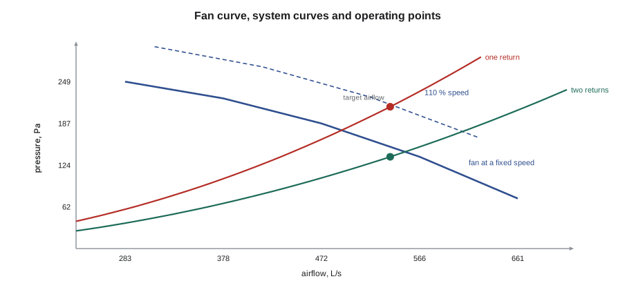
Each fan has a fan curve, from the manufacturer's tests, showing the pressure it can produce at each airflow at a given speed. As the airflow rises, the pressure it can deliver falls; the fan delivers its maximum airflow against no resistance and its maximum pressure against a closed outlet. For residential equipment the manufacturer usually gives a blower table instead of a curve: the airflow at each speed tap or setting at several values of total external static pressure.
Residential blower motors come in three kinds, as RAC-130 and RAC-230 described. A PSC motor runs at a fixed speed on each tap, so its airflow follows the fan curve and falls as the static pressure rises. A constant-torque ECM behaves similarly, holding torque rather than speed. A constant-airflow ECM measures its own speed and torque and adjusts them to hold a programmed airflow, so its airflow stays nearly steady as static rises, until it reaches its limit, but its power and noise rise.
System curves
A duct system resists airflow. Most of that resistance comes from friction in the ducts, turbulence in fittings, and the pressure drops of filters, coils, dampers and grilles, all of which rise roughly with the square of the airflow. The system curve is a parabola: double the airflow and the system needs four times the pressure. One measured point, a total external static pressure at a known airflow, fixes the whole curve.
The fan and the system must agree: the fan delivers the airflow at which the pressure it produces equals the pressure the system needs. That operating point is where the fan curve crosses the system curve. Adding resistance, such as a dirty filter, a closed damper, a crushed flexible duct or an undersized return, steepens the system curve and moves the operating point to a lower airflow and higher pressure. Removing resistance does the opposite.
Total external static pressure, TESP, is the pressure the blower must provide outside its own cabinet: the static pressure in the supply duct just after the unit minus the static pressure in the return just before it, with the return reading negative so the two add. Manufacturers' blower tables are given against TESP, and the components inside the cabinet, such as the blower housing and, in many furnaces, the filter rack, are already accounted for. Items outside the cabinet, such as an add-on coil or an external filter, count against the available static.
The fan laws
For a given fan and system, three fan laws describe what happens when the fan speed changes. Airflow is proportional to speed; pressure is proportional to the square of speed; and power is proportional to the cube of speed. So a 10 % increase in speed gives about 10 % more airflow, 21 % more pressure and 33 % more power. The laws apply as long as the system curve stays the same, because a fan moving along a fixed system curve stays at the same relative point on its own curve.
The cube law is why reducing fan speed saves so much energy, and why a variable-speed blower running at half speed for most of the year uses a small fraction of its full-speed power. It is also why forcing more air through a restrictive system costs so much: every extra bit of airflow needs disproportionately more power.
The power the fan delivers to the air, the air power, is the airflow times the pressure rise. The motor's electrical power is larger, by the combined efficiency of the fan and motor, which for small residential blowers is often only about 25 to 45 %.
P_{\text{air}} = \dot{V} \times \Delta p \quad \text{W (}\dot{V}\ \text{in m}^3/\text{s},\ \Delta p\ \text{in Pa)}
The Novak blower
Marcus's notes from the Novak start-up gave the two measured points: 212 Pa at the target 539 L/s with only the original return, and 137 Pa at the same airflow after the second return was cut in. The script converts velocity pressures to velocities for later, builds both system curves from those points, finds where each meets a fixed-speed fan curve similar to the air handler's at one setting, uses the fan laws to find the speed needed on the old system, and compares the blower power.
import math
# 1. velocity pressure and velocity
for vp in (25, 50, 100):                         # Pa
    print(f"velocity pressure {vp:3d} Pa -> air velocity {math.sqrt(vp / 0.602):.1f} m/s (standard air)")
# 2. a fan at a fixed speed (constant torque) against two duct systems
fan = [(280, 250), (380, 225), (470, 187), (570, 137), (660, 75)]   # (L/s, Pa) at this speed
def fan_p(q):
    for (q1, p1), (q2, p2) in zip(fan, fan[1:]):
        if q1 <= q <= q2:
            return p1 + (p2 - p1) * (q - q1) / (q2 - q1)
    raise ValueError(q)
def operating(k):
    lo, hi = 280, 660
    for _ in range(60):
        m = (lo + hi) / 2
        lo, hi = (m, hi) if fan_p(m) > k * m * m else (lo, m)
    return m, fan_p(m)
k_old = 212 / 539 ** 2          # one return: 212 Pa total external static at 539 L/s
k_new = 137 / 539 ** 2          # second return added: 137 Pa at the same airflow
for name, k in (("one return", k_old), ("two returns", k_new)):
    q, p = operating(k)
    print(f"{name:12s}: system curve meets the fan at {q:.0f} L/s and {p:.0f} Pa")
# 3. fan laws: speed needed for the target airflow on the old system, and the power
target = 539
q1, p1 = operating(k_old)
n_ratio = target / q1
print(f"to reach {target} L/s on the old ducts the fan needs {n_ratio:.0%} of its speed: "
      f"pressure x{n_ratio ** 2:.2f}, power x{n_ratio ** 3:.2f}")
# 4. power at the target airflow: air watts = L/s x Pa / 1000, fan and motor efficiency about 35 %
for name, p in (("one return", 212), ("two returns", 137)):
    air_w = target * p / 1000
    print(f"{name:12s}: air power {air_w:.0f} W, electrical about {air_w / 0.35:.0f} W")
saving = (212 - 137) * target / 1000 / 0.35 * 4000 / 1000
print(f"at about 4,000 h of blower operation a year, the second return saves about {saving:.0f} kWh")velocity pressure 25 Pa -> air velocity 6.4 m/s (standard air) velocity pressure 50 Pa -> air velocity 9.1 m/s (standard air) velocity pressure 100 Pa -> air velocity 12.9 m/s (standard air) one return : system curve meets the fan at 491 L/s and 176 Pa two returns : system curve meets the fan at 554 L/s and 145 Pa to reach 539 L/s on the old ducts the fan needs 110% of its speed: pressure x1.20, power x1.32 one return : air power 114 W, electrical about 326 W two returns : air power 74 W, electrical about 211 W at about 4,000 h of blower operation a year, the second return saves about 462 kWh
With only the original return, a fixed-speed fan at that setting would have delivered only about 491 L/s; to reach 539 L/s it would have needed about 10 % more speed, 20 % more pressure and a third more power. The variable-speed blower did exactly that on its own, which is why it was loud. With the second return the same airflow needed about 211 W instead of about 326 W, saving about 460 kWh a year at the blower's long running hours.
Theo understood now. A constant-airflow blower hides a restrictive duct system by working harder, so the airflow at start-up looks right while the noise, the power and the wear on the motor are not. A PSC blower in the same system would simply have delivered too little air, and the heat pump would have run with high head pressure in heating and a cold, frosty coil in cooling. Either way, the duct system is the problem, and the static pressure reading is how you find it.
Reading static pressure in the field
Northfield measured static pressure on every start-up and service visit with a digital manometer and static pressure tips: short probes with side holes, inserted through 9 mm (3/8 in.) holes drilled in the duct, with the tip pointing into the airflow so the side holes read static pressure only. The standard test points are the supply plenum after the air handler, before any branch takeoff; the return duct before the air handler and, where there is one, before and after an external filter; and before and after an add-on coil. With those readings a technician can see where the pressure is going.
At the Novak start-up, before the second return, the readings had been a return static of −145 Pa, of which the filter and the single return grille and duct took most, and a supply static of +67 Pa. The return side was taking more than twice the supply side, which pointed straight at it. After the second return, the return static fell to about −70 Pa.
Typical guidance for residential systems is that no single component should take more than a reasonable share of the rated external static, that filter pressure drop should be checked against its rating when clean and replaced well before it doubles, and that a total external static pressure well above the equipment's rating is a sign of undersized ducts or added restrictions. NCI and ACCA training programs, which Northfield's technicians had taken, use these readings as a routine diagnostic.
Common mistakes
MistakeChecking airflow only by whether a variable-speed blower reaches its setting.
InsteadMeasure static pressure; a constant-airflow blower hides restrictive ducts by working harder.
MistakeMeasuring static pressure with a plain tube held at an angle in the airflow.
InsteadUse a static pressure tip with side holes, pointed into the airflow.
MistakeAdding a filter or coil outside the cabinet without allowing for its pressure drop.
InsteadCount every external component against the available static.
MistakeExpecting more speed to fix low airflow cheaply.
InsteadPower rises with the cube of speed; fix the restriction instead.
MistakeIgnoring the return side.
InsteadUndersized returns are one of the commonest causes of high static pressure.
Summary and key terms
- Duct air has static, velocity and total pressure; total pressure always falls along the flow.
- A fan curve shows the pressure a fan can produce at each airflow; residential tables give airflow against TESP.
- A system's resistance rises with the square of airflow; one measured point fixes its system curve.
- The operating point is where the fan and system curves cross; added resistance lowers the airflow.
- Airflow is proportional to fan speed, pressure to its square and power to its cube.
- Static pressure readings at standard test points locate restrictions; constant-airflow blowers hide them.
- Static pressure
- The pressure in a duct that acts equally in all directions and pushes air through resistance.
- Velocity pressure
- The pressure due to the air’s motion, equal to half the density times velocity squared.
- Total pressure
- The sum of static and velocity pressure.
- Total external static pressure (TESP)
- The pressure the blower provides outside its cabinet: supply static minus return static.
- Fan curve
- The pressure a fan produces at each airflow at a given speed.
- System curve
- The pressure a duct system needs at each airflow, rising with airflow squared.
- Operating point
- The airflow and pressure where the fan curve and system curve cross.
- Fan laws
- Rules relating airflow, pressure and power to fan speed for a fixed system.
- Pitot tube
- A probe that measures total and static pressure, and so velocity pressure.
Practice problems
Work each problem on paper first, then reveal the answer to check.
A system needs 100 Pa at 400 L/s. What does it need at 500 L/s?
Show answer
100 × (500/400)² ≈ 156 Pa.
A fan's speed is cut to 80 %. What happens to its airflow, pressure and power on the same system?
Show answer
Airflow 80 %, pressure 64 %, power about 51 %.
Supply static is +75 Pa and return static −100 Pa. What is the TESP?
Show answer
175 Pa.
A pitot traverse reads a velocity pressure of 25 Pa. What is the velocity?
Show answer
About 6.4 m/s.
Lesson quiz · 5 questions
Score 60% or more to complete this lesson.
Create a free account to save your progress, take quizzes and earn a certificate.