
RAC-330 · Lesson 12 of 12 · 17 min
Airflow and indoor air quality commissioning: the capstone
By the end of May both of Theo's spring projects were ready for their final checks. At the Novak house the basement ducts, the new outlets, the jump duct, the media filter and the HRV were all in, and the ceiling was closed. At the clinic, the outlets had been rebalanced and the packaged heat pump's dehumidification mode was ready to be set up before the humid weather. Dana asked Theo to commission both and to write the reports himself, with Marcus checking. "This is the course in two jobs," she said. "Show me you can prove they work."
This lesson pulls the course together. It sets out a commissioning procedure for airflow, ventilation and indoor air quality on a house and a small commercial building, works through the two jobs, and lists the records that should be left with the owner.
What commissioning means here
RAC-320 lesson 10 commissioned the refrigeration side of a heat pump: charge, both modes, defrost, controls. This course's commissioning is about the air: that each room gets its design airflow, that the system's static pressure is reasonable, that the ventilation rates are delivered and balanced, that filters and outlets are as designed, and that the rooms reach their comfort and humidity targets. In commercial work this is part of the testing, adjusting and balancing and the commissioning process that CSA Z320 and ASHRAE Guideline 0 and Standard 202 describe; in houses it is what ACCA's quality installation standards and good contractors expect.
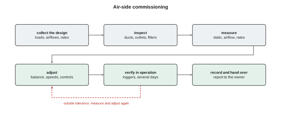
The procedure has the same shape for both jobs:
- Collect the design: loads, room airflows, outlet schedule, ventilation rates, equipment data, filter specification and setpoints.
- Inspect: ducts sealed and supported, dampers in place and marked, outlets as specified and aimed, filters fitted without gaps, ventilator ducts insulated and the intake and exhaust properly separated.
- Measure: total external static pressure and its parts; total airflow by two methods; each outlet with a flow hood; ventilator supply and exhaust; temperature split or rise; and, where relevant, duct leakage, room pressures with doors closed, humidity and CO2.
- Adjust: balance outlets and branches, set blower and ventilator speeds, set humidity and ventilation controls.
- Verify the result in operation, preferably over several days with data loggers, and record everything.
The Novak house
Theo started at the air handler. He measured the static pressure at the test ports, then the airflow by two methods, the air handler's own display and the temperature rise on the heater kit's first stage, which agreed within about 5 %. Then he went room by room with the flow hood, adjusting the branch dampers he and Marcus had installed, and finished with the HRV, whose supply and exhaust flow stations he read with the manometer and balanced with its dampers. The script compares his final readings with the design.
import math
def p_atm(z_m):
    """Standard atmospheric pressure, kPa, at an elevation in metres."""
    return 101.325 * (1 - 2.25577e-5 * z_m) ** 5.2559
def pws(t):
    """Saturation pressure of water vapour over water, kPa, t in deg C (Magnus form)."""
    return 0.61094 * math.exp(17.625 * t / (t + 243.04))
def w_from_rh(t, rh, p):
    """Humidity ratio, kg of water per kg of dry air."""
    pv = rh * pws(t)
    return 0.622 * pv / (p - pv)
def pv_from_w(w, p):
    return w * p / (0.622 + w)
def dew_point(pv):
    a = math.log(pv / 0.61094)
    return 243.04 * a / (17.625 - a)
def enthalpy(t, w):
    """kJ per kg of dry air."""
    return 1.006 * t + w * (2501 + 1.86 * t)
def spec_volume(t, w, p):
    """Cubic metres per kg of dry air."""
    return 0.287042 * (t + 273.15) * (1 + 1.607858 * w) / p
def wet_bulb(t, w, p):
    """Thermodynamic wet-bulb temperature found by bisection."""
    lo, hi = -40.0, t
    for _ in range(60):
        m = (lo + hi) / 2
        ws = w_from_rh(m, 1.0, p)
        wc = ((2501 - 2.326 * m) * ws - 1.006 * (t - m)) / (2501 + 1.86 * t - 4.186 * m)
        lo, hi = (lo, m) if wc > w else (m, hi)
    return (lo + hi) / 2
def rel_humidity(t, w, p):
    return pv_from_w(w, p) / pws(t)

P = p_atm(330)
# 1. Novak commissioning: room airflows against design, HRV balance and static pressure
design = {"living": 85, "kitchen": 55, "dining": 45, "main bedroom": 50, "bedroom 2": 40, "bedroom 3": 40, "bath": 20,
          "recreation (2 outlets)": 110, "basement office": 50, "basement bath": 24, "laundry and mechanical": 20}
measured = {"living": 82, "kitchen": 57, "dining": 44, "main bedroom": 47, "bedroom 2": 41, "bedroom 3": 38, "bath": 21,
            "recreation (2 outlets)": 104, "basement office": 52, "basement bath": 23, "laundry and mechanical": 19}
out = [k for k in design if not 0.9 <= measured[k] / design[k] <= 1.1]
print(f"supply total {sum(measured.values())} of {sum(design.values())} L/s; rooms outside +/-10 %: {out or 'none'}")
hrv_sup, hrv_exh = 22, 21
print(f"HRV supply {hrv_sup} L/s, exhaust {hrv_exh} L/s, imbalance {abs(hrv_sup - hrv_exh) / hrv_exh:.0%}")
tesp = 64 + 70                                # supply +64 Pa, return -70 Pa
print(f"total external static {tesp} Pa (137 Pa at the second-return start-up; the new media filter took a little off)")
# 2. clinic operatory humidity: room moisture is removed by the supply air
latent_room = 650                              # W of moisture load in one operatory on a humid afternoon
def room_state(q_ls, w_supply, t_room=24.0):
    w_room = w_supply + latent_room / (3010 * q_ls)
    return rel_humidity(t_room, w_room, P)
w_s_normal = w_from_rh(13.0, 0.92, P)          # supply air from lesson 3
w_s_dry = w_from_rh(12.0, 0.92, P)             # dehumidification mode: lower blower speed, colder coil
print(f"before: 90 L/s at {w_s_normal * 1000:.1f} g/kg -> operatory {room_state(90, w_s_normal):.0%} RH")
print(f"after balancing: 110 L/s -> {room_state(110, w_s_normal):.0%} RH")
print(f"after balancing + dehumidification mode ({w_s_dry * 1000:.1f} g/kg) -> {room_state(110, w_s_dry):.0%} RH")supply total 528 of 539 L/s; rooms outside +/-10 %: none HRV supply 22 L/s, exhaust 21 L/s, imbalance 5% total external static 134 Pa (137 Pa at the second-return start-up; the new media filter took a little off) before: 90 L/s at 8.9 g/kg -> operatory 58% RH after balancing: 110 L/s -> 56% RH after balancing + dehumidification mode (8.3 g/kg) -> 53% RH
The outlets totalled 528 L/s against a design of 539 L/s, and every room was within 10 % of its design, including the recreation room's two new outlets, which together delivered 104 L/s of the 110 L/s design. The HRV's supply and exhaust were within 5 % of each other. The total external static pressure was 134 Pa, slightly lower than at the second-return start-up because the new media filter had less resistance than the old one.
He then checked the things the airflow numbers could not show. With the daughter's bedroom door closed, the room measured about 2 Pa above the hallway, as lesson 10 had predicted with the jump duct. The recreation room's two ceiling outlets threw their air down the exterior wall; with the smoke pencil he could see it washing the windows. The HRV's intake and exhaust hoods were properly separated on the side wall, its outdoor ducts insulated and sealed, and its condensate drain trapped and running to the floor drain. The HRV was on low continuous speed, with the bathroom boost timers and the dehumidistat set as lesson 11 described.
Finally, he left two small data loggers in the house for a week, one in the recreation room and one in the main bedroom, recording temperature and humidity. When he collected them, the recreation room had stayed within about 1 K (2 °F) of the main floor all week, for the first time since the Novaks had owned the house, and the humidity had settled at 35 to 45 % in mild spring weather, which the HRV's dehumidistat had held.
The clinic
At the clinic, the balancing from lesson 8 had brought every outlet within 10 % of design, with the operatories now getting their full share. What remained was the humidity. Marcus and Theo set up the packaged unit's dehumidification mode, which lowered the blower speed when the return-air humidity rose above a setpoint, making the coil colder and drier, as lesson 3 explained, and confirmed in the controller that the mode was limited so that the coil could not freeze and the airflow could not fall below the minimum for the heat strips or the ventilation air. They set the clinic's thermostat to 23 °C (74 °F) during patient hours, a compromise between the dental staff, who were active and gowned, and patients, who were seated.
The script's second part estimated what the changes would do to an operatory on a humid afternoon, using the room's moisture load from the original design and the supply air from lesson 3. Before balancing, with about 90 L/s at the normal supply humidity, the operatory would have settled at about 58 % relative humidity, matching what the staff had felt. Balancing to its design 110 L/s brought it to about 56 %, and the dehumidification mode, with drier supply air, to about 53 %. Neither change alone would have done it; together they kept the operatories near the middle of the comfort range in lesson 4.
The clinic also got a CO2 and humidity sensor in each operatory, connected to the unit's controller, so that its demand-controlled ventilation and dehumidification responded to the rooms that needed them most, not to the return air average. Theo verified each sensor against his calibrated meter. In July, on the first humid week, Dr. Singh sent a short message: "The operatories are fine. Thank you."
The records
The reports were the part Dana cared about most. Each one had the design values, the instruments used and their calibration dates, the readings before and after adjustment, the damper positions, the control settings and their reasons, the data logger results and a short list of recommendations. For the Novaks, the recommendations were to replace the media filter once a year, wash the HRV filters every three months, lower the HRV speed on the coldest winter days if the house felt dry, and consider an ERV core if it still did. For the clinic, they were to check the operatory sensors annually against a calibrated meter, keep the balancing damper positions as marked, and review the humidity trends after the first full summer.
A good record turns the next service call from a guessing game into a comparison. When something changes, a technician with the commissioning report can see what the system did when it was right.
Looking back over the course
Theo's year on the comfort side had followed a path that this course traced. The Novaks' sweating windows were a dew point problem; the produce area's droplets, a chart reading; the clinic's clammy operatories, a sensible heat ratio and an airflow problem; the residents' cold mornings, a radiant and air distribution problem; the four-ton quote, a load calculation problem; the noisy blower, a static pressure problem; the cold recreation room, a duct and outlet problem; the stuffy bedroom, a return path problem; and the windows again, finally, a ventilation problem. Each had looked like an equipment complaint, and in each the equipment was working. The answers were in the air.
RAC-410 moves on to chillers and large systems, where the same psychrometrics and airflow principles apply to air handlers and the same pressure and flow principles to water. The habit this course tries to build carries into all of them: measure the air, draw it on the chart, and prove the result.
Handing over to the owner
Commissioning ends with the people who will live or work with the system. Theo walked Irene and Pavel Novak through their house with the report in hand: where the filter cabinet was and how to change the filter; where the HRV's controls and filters were and what the dehumidistat did; which registers and returns must stay uncovered; which dampers had been set and marked, and why they should not be moved; and what to watch for, such as condensation returning on the coldest days or the recreation room drifting cooler, that should prompt a call. Irene asked for the commissioning data in a spreadsheet, which Theo sent her.
At the clinic, the handover was to Dr. Singh and the office manager, with a one-page summary posted in the mechanical closet: the dehumidification setting, the operatory sensor locations and the balancing record. Marcus added the clinic to Northfield's list for a short follow-up visit after the first humid month, to compare the sensor trends with the commissioning readings, because a system that works on handover day can drift as people adjust it.
Common mistakes
MistakeCommissioning only the refrigeration side of a system.
InsteadCommission the air side too: static, airflow, outlets, ventilation and humidity.
MistakeMeasuring total airflow by one method only.
InsteadUse two methods that should agree, and investigate if they do not.
MistakeBalancing without recording damper positions.
InsteadMark and record positions so they can be checked and reset.
MistakeAccepting humidity and CO2 sensors without checking them.
InsteadVerify sensors against a calibrated instrument at commissioning.
MistakeLeaving the job without verifying operation.
InsteadLog temperature and humidity in operation, ideally for several days.
Summary and key terms
- Air-side commissioning collects the design, inspects, measures, adjusts and verifies in operation.
- Airflow is checked in total by two methods and at every outlet against design, typically within ±10 %.
- Ventilators are measured and balanced; room pressures, throw and return paths are checked.
- Humidity problems often need both correct airflow to the right rooms and drier supply air.
- Sensors used by controls are verified against calibrated instruments.
- A complete record of design, readings, settings and recommendations is left with the owner.
- Commissioning
- A process of verifying and documenting that systems are installed and work as designed.
- Data logger
- A small instrument that records temperature, humidity or other readings over time.
- Dehumidification mode
- A control mode that lowers airflow or adds reheat to remove more moisture.
- Smoke pencil
- A device that releases a thin stream of visible vapour to show air movement.
- Flow station
- A built-in device for measuring airflow in a ventilator or duct.
- Recommissioning
- Repeating commissioning checks later in a system’s life to restore performance.
Practice problems
Work each problem on paper first, then reveal the answer to check.
An outlet's design is 55 L/s (115 cfm) and it measures 50 L/s (105 cfm). Is it within ±10 %?
Show answer
Yes, it is about 91 % of design.
Name two methods to check total airflow on a residential heat pump.
Show answer
Any two of: blower table with static pressure, temperature rise on electric heat, a powered flow meter, the equipment's own display.
Why did the clinic need both balancing and a dehumidification mode?
Show answer
Balancing delivered enough air to the operatories; the mode made that air drier.
What should a commissioning record include?
Show answer
Design values, instruments and calibration, readings before and after, settings, logger results and recommendations.
Lesson quiz · 5 questions
Score 60% or more to complete this lesson.
Create a free account to save your progress, take quizzes and earn a certificate.