
RAC-330 · Lesson 5 of 12 · 17 min
Heating loads
When the Novaks first asked about a heat pump, the quote they received from another contractor had sized the system by floor area: 240 m² at 60 W per square metre, a four-ton unit. Northfield's quote was for a three-ton cold-climate heat pump, because Dana had insisted on a calculated heat loss, and RAC-320 lesson 7 followed that decision. In January, with the house running well, Irene asked Theo to show her how the calculation worked. "I'm an engineer," she said. "I'd like to see the numbers, not just the answer." Theo was glad of the excuse to go through them properly.
This lesson explains how a heating load is calculated: the design temperatures, heat loss through each part of the envelope, air leakage, below-grade losses, and how CSA F280 organizes the work. Lesson 6 does the same for cooling.
What a heating load is
The design heating load is the rate at which a building loses heat on a cold day near the coldest of a typical winter, with the inside held at the design indoor temperature. It is the capacity the heating system must supply. It is not the coldest day ever recorded, and it is not the energy used over a season, which depends on the whole winter's weather and is estimated separately, as RAC-320 lesson 12 did with degree-days.
Heat leaves a building in two main ways. It is conducted through the walls, windows, doors, roof, basement and floor, at a rate proportional to the area of each part, its thermal transmittance and the temperature difference across it. And it is carried away by air: outdoor air that leaks in through cracks and is heated, and indoor air that leaves through exhaust fans, chimneys and ventilation. In houses, the two are often similar in size; in a leaky older house the air can be the larger.
Design temperatures
The outdoor design temperature comes from published climate data. In Canada, the National Building Code's climatic data, which provincial codes adopt, give the January 2.5 % design temperature for each location: the temperature that the hourly outdoor temperature falls below for only 2.5 % of the hours in January. For Kitchener it is about −19 °C. Colder spells happen, and the house cools slightly during them or the supplementary heat makes up the difference, but sizing to the extreme would oversize the equipment for every other day.
The indoor design temperature is set by the standard: 22 °C in CSA F280 for living spaces, with lower values for unfinished basements. It is a design value, not the setpoint the family will choose.
Conduction through the envelope
Each part of the envelope has a U-value, its thermal transmittance, the heat flow through one square metre or square foot for each degree of temperature difference. It is the inverse of the total thermal resistance, RSI in Canada, in m²·K/W, or R in US units, in ft²·°F·h/Btu, where R = RSI × 5.678. The resistance of a wall is the sum of its layers' resistances, including the air films on each surface, but framing members, which conduct heat much better than insulation, form thermal bridges through it. The effective resistance of a wood-framed wall is therefore noticeably lower than the nominal value of the insulation in it, and calculation standards use effective values.
Windows and doors use the manufacturer's rated U-value, or a typical value for the type and age when no rating is available. A 1960s double-glazed window in a wood or steel frame might be 2.5 to 3.0 W/m²·K; a modern triple-glazed unit under 1.0; so windows, though a small part of the area, are often a large part of the loss.
Areas are measured from the drawings or on site: gross wall area, minus windows and doors, for each orientation; ceiling area under the attic; and the below-grade parts of the basement. CSA F280 calculations are normally done room by room, because the room loads set the airflow to each room, which lesson 9 uses to size ducts. For the whole-house total, a single calculation for each component type is enough.
Below-grade losses
Basement walls and floors lose heat to the soil, which is warmer than the outdoor air in winter and cooler deep down than near the surface. Heat flow through the upper part of a basement wall is much higher than through the lower part, and the floor loses relatively little, mostly near its edges. The standards handle this with tables or formulas that give effective U-values for below-grade walls by depth and insulation, and for floors by their size and edge insulation, against either the outdoor design temperature or a ground temperature. The Novak basement walls had RSI 1.8 (R-10) insulation on the upper half only, added when the basement was finished in the 1990s.
Air leakage
Air leakage is the hardest part of the load to estimate, because it depends on the size and location of the leaks and on the wind and the stack effect, the tendency of warm air to rise out through the top of a heated house and draw cold air in at the bottom. There are two common approaches.
- Estimate leakage from the construction quality, using the standard's tables for tight, average or loose construction.
- Measure it with a blower door, a calibrated fan in an exterior doorway that depressurizes the house to 50 Pa and measures the airflow needed. The result is expressed as air changes per hour at 50 Pa, ACH50. A rough rule divides ACH50 by a factor of about 10 to 20, depending on the climate, the number of storeys and the exposure, to estimate the natural air change rate on an average winter day. More detailed methods use the measured leakage area and the design wind and temperature difference.
The heat needed to warm the leaking air is the airflow times the sensible heat factor times the temperature difference. For a natural air change rate in air changes per hour, the airflow is that rate times the house volume.
Q_{\text{air}} = 0.335 \times \text{ACH} \times V \times \Delta T \quad \text{W (V in m}^3)
The Novaks had had a blower door test before and after the air sealing, as part of their energy audit. Before: about 8.0 ACH50. After sealing the attic hatch, the top plates, the old chimney chase and the rim joists: about 4.0 ACH50. Theo used a factor of 14, a typical value for a one-storey house in a sheltered suburb, and labelled it as an estimate.
The Novak calculation
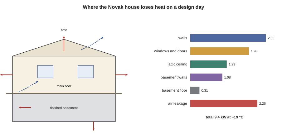
The script follows the calculation Theo had done in the office, one line for each component type, with the areas from the house drawings and effective U-values from the standard's tables and the window ratings. It then compares the leakage before and after the air sealing, and checks the heat pump's capacity at the design temperature, from RAC-320 lesson 6.
T_IN, T_OUT = 22.0, -19.0          # CSA F280 indoor design and Kitchener's January design temperature
dT = T_IN - T_OUT
V = 240 * 2.4                       # m3 of heated volume, main floor and finished basement
def infiltration_ua(ach50, n=14):
    """Natural air change rate from a blower-door result, then W per K (0.335 Wh per m3 per K)."""
    ach = ach50 / n
    return 0.335 * ach * V, ach
parts = [
    # name, area m2, U-value W/(m2 K)
    ("walls above grade", 87.6, 0.71),
    ("windows and doors", 21.0, 2.30),
    ("attic ceiling (after upgrade)", 120.0, 0.25),
    ("basement walls below grade", 88.0, 0.30),
    ("basement floor", 120.0, 0.063),
]
ua_total = 0
for name, area, u in parts:
    ua = area * u; ua_total += ua
    print(f"{name:32s} {area:6.1f} m2 x U {u:5.3f} = {ua:5.1f} W/K -> {ua * dT / 1000:5.2f} kW")
ua_inf, ach = infiltration_ua(4.0)
ua_total += ua_inf
print(f"{'air leakage (4.0 ACH50)':32s} {ach:.2f} air changes per hour      = {ua_inf:5.1f} W/K -> {ua_inf * dT / 1000:5.2f} kW")
loss = ua_total * dT / 1000
print(f"total UA {ua_total:.0f} W/K, design heat loss {loss:.1f} kW at {T_OUT:.0f} C")
before, _ = infiltration_ua(8.0)
print(f"before air sealing (8.0 ACH50) the leakage alone was {before * dT / 1000:.2f} kW")
hp = 8.1
print(f"heat pump at design {hp} kW covers {hp / loss:.0%}; the rest comes from the heater kit")walls above grade 87.6 m2 x U 0.710 = 62.2 W/K -> 2.55 kW windows and doors 21.0 m2 x U 2.300 = 48.3 W/K -> 1.98 kW attic ceiling (after upgrade) 120.0 m2 x U 0.250 = 30.0 W/K -> 1.23 kW basement walls below grade 88.0 m2 x U 0.300 = 26.4 W/K -> 1.08 kW basement floor 120.0 m2 x U 0.063 = 7.6 W/K -> 0.31 kW air leakage (4.0 ACH50) 0.29 air changes per hour = 55.1 W/K -> 2.26 kW total UA 230 W/K, design heat loss 9.4 kW at -19 C before air sealing (8.0 ACH50) the leakage alone was 4.52 kW heat pump at design 8.1 kW covers 86%; the rest comes from the heater kit
The total UA came to about 230 W/K and the design heat loss to 9.4 kW at −19 °C. The walls and the air leakage were the two largest parts, each about a quarter of the total, and the windows came next. The air sealing had cut the leakage load from about 4.5 kW to 2.3 kW, which on its own was the difference between a three-ton and a four-ton heat pump. At the design temperature the cold-climate heat pump's 8.1 kW covered 86 % of the load.
Irene checked the attic line and asked why it was so modest, since the attic had been insulated. Theo explained that the low roof over the eaves limited the insulation depth near the walls, and the effective value included the framing and the less-insulated areas around the hatch and the old chimney; about RSI 4 effective (R-23) over the whole ceiling was a fair estimate. Irene also asked about the floor-area rule. Theo showed her that 60 W per square metre would have given about 14.4 kW, half again as much as the real loss, because the rule assumes an average house and the Novaks' was now tighter and better insulated than average.
CSA F280 and Manual J
CSA F280, Determining the Required Capacity of Residential Space Heating and Cooling Appliances, is the Canadian standard for house heating and cooling loads, and the Ontario Building Code requires a calculation to it, done by a qualified designer, for the heating and cooling equipment in a new house or a replacement that changes the system. It specifies the design conditions, the U-value and below-grade methods, the air leakage estimate, and the room-by-room procedure, and it sets limits on how much larger than the calculated load the equipment may be.
Both are normally done with software, which applies the tables and adds up the rooms. The technician's job is to give the software good inputs: measured areas, real window ratings, the insulation actually found in the walls and attic, a blower door result when there is one, and the correct design temperatures. Most errors in load calculations are not errors in arithmetic but guesses about the building: assuming insulation that is not there, or ignoring a large basement window.
Ventilation and other gains and losses
If a house has mechanical ventilation, the heat needed to warm the ventilation air is part of the load, reduced by the heat recovery of an HRV or ERV, as lesson 11 shows. Duct losses add to the load when ducts run through unheated spaces such as a vented attic or crawlspace; the Novaks' ducts were all inside the heated basement, so their losses stayed in the house. Internal gains from people, lighting and appliances reduce the heating needed on most days, but heating calculations usually ignore them, because the design day might be a night with nobody home.
Common mistakes
MistakeSizing heating equipment by floor area.
InsteadCalculate the load from the envelope, air leakage and design temperatures.
MistakeUsing the coldest temperature ever recorded as the design temperature.
InsteadUse the published design temperature from the code's climate data.
MistakeUsing nominal insulation values for framed walls.
InsteadUse effective values that include the framing.
MistakeIgnoring air leakage or guessing it without a test.
InsteadUse a blower door result where possible and label estimates.
MistakeForgetting below-grade walls and basement windows.
InsteadInclude every part of the heated envelope, by room.
Summary and key terms
- The design heating load is the heat loss at the design outdoor and indoor temperatures.
- Conduction loss for each component is U times area times temperature difference; U is the inverse of total resistance.
- Framing reduces the effective resistance of walls; window U-values matter more than their area suggests.
- Below-grade walls and floors use effective U-values from the standard's tables.
- Air leakage, best estimated from a blower door test, is often as large as the wall loss.
- CSA F280 organizes the room-by-room calculation; good inputs matter more than the software.
- Design heating load
- The rate of heat loss at the design indoor and outdoor temperatures.
- Design temperature
- A published outdoor temperature used for sizing, exceeded only rarely in a typical year.
- U-value
- Thermal transmittance: heat flow per unit area per degree of temperature difference.
- Thermal resistance (RSI or R)
- Resistance to heat flow; the inverse of the U-value.
- Thermal bridge
- A part of the envelope, such as framing, that conducts heat much better than the insulation around it.
- Blower door
- A calibrated fan used to measure a building’s air leakage.
- ACH50
- Air changes per hour at a 50 Pa pressure difference, from a blower door test.
- Stack effect
- Air movement caused by warm indoor air rising and leaving through the top of a building.
Practice problems
Work each problem on paper first, then reveal the answer to check.
A wall of 20 m² has a U-value of 0.40 W/m²·K. What does it lose with a 40 K difference?
Show answer
0.40 × 20 × 40 = 320 W.
A layer has RSI 3.5. What is its R-value?
Show answer
About R-20.
A house tests at 7.0 ACH50. Using a factor of 14, what natural air change rate would you estimate?
Show answer
About 0.5 air changes per hour.
Why are heating loads calculated room by room?
Show answer
Room loads set the airflow each room needs, which sizes the ducts and outlets.
Lesson quiz · 5 questions
Score 60% or more to complete this lesson.
Create a free account to save your progress, take quizzes and earn a certificate.