
RAC-310 · Lesson 8 of 12 · 17 min
Rack controls: suction and head pressure, case control and defrost
The week before Harvest Lane opened, the medium-temperature rack had been running for four days with the cases loaded with water jugs to simulate product. Every fixture held temperature except one: the butcher's service case, which hovered at 3 °C (38 °F) when it was supposed to hold 0 °C (32 °F). Its controller showed the liquid solenoid open all the time and the superheat normal. Raj connected a gauge to the access port at the inlet of the circuit's evaporator pressure regulator in the machine room and read a pressure that corresponded to −2 °C (28 °F). "That regulator is set for produce," he said. "Someone copied the settings down the whole line." Ten minutes and a quarter turn of the regulator's adjusting stem later, the case began to cool.
A rack's controls have three jobs: hold the suction pressure so every fixture can get the refrigerant it needs, hold the condensing pressure as low as the system allows while still feeding the expansion devices, and coordinate the defrosts and heat reclaim. Each fixture also has its own controls that decide when it takes refrigerant. This lesson covers both levels, building on the controls of RAC-230.
Suction pressure control
The rack controller measures the suction header pressure with a transducer, converts it to a saturated temperature for the refrigerant, and stages or modulates the compressors to hold it at a setpoint. Typical parameters are a setpoint, a deadband or neutral zone around it in which nothing changes, delays before adding or removing a stage, minimum run and off times for each compressor, and limits on starts per hour. A variable-speed lead, as lesson 7 showed, is controlled by a PI loop that changes its speed to hold the setpoint more closely.
The suction setpoint must be low enough for the coldest fixture on the rack to get its required evaporating temperature, but every degree lower costs energy, roughly a few per cent of compressor power per kelvin of lift. Many rack controllers therefore use floating suction, also called suction reset: they read each case controller's demand over the network and raise the suction setpoint gradually while every fixture is satisfied, lowering it again when any fixture starts to lose temperature. A floating suction strategy can save a useful amount of energy, but it must have limits set sensibly, or the fixture with the least margin will be warm whenever the setpoint drifts up.
| Parameter | Purpose | What goes wrong |
|---|---|---|
| Suction setpoint | Evaporating temperature for the coldest fixture | Set too high: warm cases; too low: wasted energy, coil frosting |
| Deadband and stage delays | Stop compressors cycling on small pressure changes | Too narrow: short cycling; too wide: large pressure swings |
| Minimum run and off times | Protect compressors from short cycling | Missing after a controller replacement |
| Floating suction limits | Range over which the setpoint may rise | Upper limit too high for the fixture with least margin |
| Compressor rotation | Even out run hours | One compressor always lead, wearing out first |
Controlling each fixture
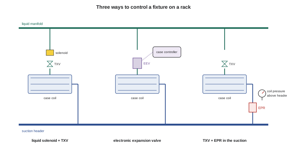
Every fixture on a rack needs its own evaporating temperature and its own control of box or case temperature. Three methods are common, and many stores have a mixture of them.
- Liquid line solenoid cycling: the case controller opens and closes a solenoid valve in the circuit's liquid line, starting and stopping the refrigerant feed to a thermostatic expansion valve. The case's evaporator runs at roughly the rack's suction temperature whenever it is fed.
- Evaporator pressure regulators, or EPRs: a valve in the circuit's suction line, set to hold the evaporator's pressure above the rack's suction pressure. It lets a fixture that needs a warmer coil, such as produce or a meat case with a small TD, share a rack with colder fixtures. Mechanical EPRs are set with an adjusting stem using a gauge on their inlet port; electronic EPRs are stepper-motor valves driven by the case or rack controller.
- Electronic expansion valves: the case controller drives an EEV, as RAC-220 described, controlling superheat and, on many systems, also closing or throttling the valve to control case temperature. With EEVs, many stores need fewer EPRs, and suction can float higher because each case controls its own temperature.
At Harvest Lane, Nadia had specified EEVs on the cases and walk-ins, mechanical EPRs on the meat and produce circuits that needed warmer coils than the rack's suction, and case controllers networked to the rack controller. The butcher case's EPR had been set at the factory to a produce pressure, and the installer had not changed it. Each EPR should be set during start-up to the pressure, from the refrigerant's pressure-temperature chart, that gives the fixture's design evaporating temperature, using the dew point for a zeotropic blend such as R-448A, as RAC-220 explained.
Head pressure control and floating head
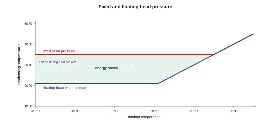
The condensing pressure on a rack is controlled by the condenser's fans and, in cold weather, by holding liquid back in the condenser with a head pressure control valve, as RAC-210 described for smaller systems. Fixed head pressure control holds a condensing temperature high enough for the worst case, typically around 32 to 38 °C (90 to 100 °F), all year. Floating head pressure lets the condensing temperature fall with the outdoor temperature, down to a minimum, which saves a large amount of compressor energy because the lift between suction and condensing temperatures falls.
The minimum condensing temperature is set by what the rest of the system needs. Thermostatic expansion valves need a minimum pressure difference across them to feed properly; EEVs can work with much smaller differences, which is one reason they allow lower minimums. Hot-gas defrost needs enough discharge pressure to push the gas through the coils. Heat reclaim needs a condensing temperature high enough to heat the store's air. The script below estimates the medium-temperature rack's yearly compressor energy with fixed head pressure and with floating head at three minimum condensing temperatures, using a simple efficiency model and typical outdoor temperatures.
# Floating head pressure on the medium-temperature rack: fixed condensing temperature versus floating with a minimum
TE = -7.0                     # C, rack saturated suction temperature
LOAD = 45.0                   # kW, average refrigeration load
ETA = 0.50                    # fraction of the ideal (Carnot) COP achieved, illustrative
APPROACH = 10.0               # K, condensing temperature above outdoor air at design airflow
# hours per year in each outdoor temperature band (illustrative, southern Ontario)
bins = {-15: 600, -5: 1800, 5: 2400, 15: 2300, 25: 1400, 30: 260}

def cop(tc):
    te_k, tc_k = TE + 273.15, tc + 273.15
    return ETA * te_k / (tc_k - te_k)

def yearly_kwh(rule):
    return sum(LOAD / cop(rule(t)) * h for t, h in bins.items())

fixed = yearly_kwh(lambda t: max(35.0, t + APPROACH))
for minimum in (27.0, 21.0, 15.0):
    floating = yearly_kwh(lambda t: max(minimum, t + APPROACH))
    print(f"floating head, minimum condensing {minimum:4.1f} C: {floating:7.0f} kWh/yr, "
f"{100 * (1 - floating / fixed):4.1f} % less than a fixed 35 C ({fixed:.0f} kWh/yr)")floating head, minimum condensing 27.0 C: 105646 kWh/yr, 15.4 % less than a fixed 35 C (124854 kWh/yr) floating head, minimum condensing 21.0 C: 94352 kWh/yr, 24.4 % less than a fixed 35 C (124854 kWh/yr) floating head, minimum condensing 15.0 C: 84613 kWh/yr, 32.2 % less than a fixed 35 C (124854 kWh/yr)
Even with the simple model, the savings are large: about a quarter (a fifth) of the rack's compressor energy at the minimum Nadia chose, 21 °C (70 °F). Going lower would save more but would need the expansion valves, the defrost and the heat reclaim to be checked at that condition. The condenser fans are usually on variable-frequency drives or staged, controlled to hold the condensing temperature at the floating target, which is the outdoor temperature plus the condenser's design approach, but never below the minimum.
Heat reclaim
A rack rejects all the heat it removes from the store, plus its compressors' input, at its condenser. In winter, much of that heat can be used to warm the store instead of being thrown away on the roof. A heat reclaim valve, a three-way valve on the discharge line, sends the discharge gas first through a heat reclaim coil in the store's air handler and then on to the roof condenser. RAC-210 introduced the idea. On a rack, the controller opens the reclaim valve when the store's heating system calls for heat, and usually raises the condensing setpoint during reclaim so the discharge gas is hot enough to heat the air usefully.
Heat reclaim is a trade-off: raising the condensing temperature costs compressor energy, but the recovered heat offsets gas or electric heating. The controller's reclaim setpoint, the condensing temperature used during reclaim, and the logic that decides when reclaim is worth running are set during commissioning with the store's mechanical contractor. A common fault is a reclaim valve that does not close fully, sending gas through the reclaim coil in summer, which raises the head pressure and can heat the store when it should be cooling. Another is reclaim that is enabled but never runs, because the air handler's controls were never told to call for it.
Defrost on racks
Rack controllers, or the case controllers they supervise, schedule each circuit's defrosts. Medium-temperature circuits usually use off-cycle defrost: the liquid solenoid or EEV closes and the case fans keep running until the coil clears. Low-temperature circuits use electric heaters or hot-gas defrost.
Hot-gas defrost on a rack sends discharge gas from the discharge header through a defrost header to the circuit being defrosted. A valve closes the circuit's suction line to the rack, a hot-gas valve opens to feed the coil, and the gas condenses in the coil as it melts the frost. The condensed liquid flows out of the coil into the liquid line through a check valve or a differential pressure valve, and is used by the other circuits. Only some circuits defrost at a time, so there is always enough load on the rack to produce the hot gas. The sequence of valves matters: opening the hot-gas valve before the suction valve closes sends hot gas straight back to the compressors, and ending defrost too quickly can return slugs of liquid. Rack and case controllers manage these sequences; the technician's job is to check that each valve opens and closes when it should, and that the defrost terminates on temperature.
Alarms and monitoring
A rack controller monitors far more than suction and discharge pressures. It typically logs each compressor's status, run hours and safety trips; the receiver level; the oil level controls; each circuit's case temperature, defrost status and valve position; the condenser's fans; the heat reclaim; the refrigerant detector; and the power supply. Alarms go to the store's monitoring service or to the refrigeration contractor's on-call technician. RAC-230 covered how to set alarm limits and delays so that people trust them. On a rack, the most important alarms are case temperatures, compressor failures, high discharge pressure, low receiver level and refrigerant leak, because each of them can lead to product loss or refrigerant loss if nobody acts.
Remote access to rack controllers is common and useful, and it brings the same defensive cybersecurity duties RAC-230 described for building automation: no default passwords, no direct exposure of controllers to the internet, remote access only through the methods the store owner approves, and accounts for each person rather than one shared login.
Common mistakes
MistakeCopying EPR settings from one circuit to another.
InsteadSet each EPR from the fixture's design evaporating temperature, using a gauge on its inlet port.
MistakeSetting floating suction limits without checking the fixture with the least margin.
InsteadSet the upper limit so the coldest fixture still holds temperature.
MistakeLowering the minimum condensing temperature without checking the expansion devices, defrost and reclaim.
InsteadConfirm each still works at the new minimum.
MistakeLeaving a heat reclaim valve that leaks through in summer.
InsteadCheck that it closes fully; watch for high head pressure and warm supply air.
MistakeOpening a hot-gas valve before the circuit's suction valve has closed.
InsteadFollow the defrost valve sequence the controller is designed for.
Summary and key terms
- The rack controller holds suction pressure by staging or modulating compressors, with deadbands, delays and minimum times.
- Floating suction raises the setpoint when all fixtures are satisfied, within limits.
- Fixtures are controlled by liquid solenoid cycling, EPRs or electronic expansion valves.
- Floating head pressure saves substantial energy, down to a minimum set by the expansion devices, defrost and reclaim.
- Heat reclaim sends discharge gas through a coil in the store's air handler when the store needs heat.
- Hot-gas defrost depends on correct valve sequencing; alarms must be trusted and acted on.
- Floating suction
- A strategy that raises a rack's suction setpoint while all fixtures are satisfied.
- Evaporator pressure regulator
- A suction line valve that holds an evaporator's pressure above the rack's suction pressure.
- Floating head pressure
- Letting the condensing pressure fall with outdoor temperature down to a minimum.
- Minimum condensing temperature
- The lowest condensing temperature a rack is allowed to float to.
- Heat reclaim
- Using rejected heat from a refrigeration system to heat a building or water.
- Hot-gas defrost
- Defrosting a coil by passing discharge gas through it.
- Neutral zone
- A band around a setpoint in which a controller makes no change.
Practice problems
Work each problem on paper first, then reveal the answer to check.
A meat case on an EPR circuit runs warm while every other case on the rack is fine. What should be checked first?
Show answer
The EPR's setting, with a gauge on its inlet port, against the case's design evaporating temperature.
Why do EEVs allow a lower minimum condensing temperature than thermostatic valves?
Show answer
They can feed correctly with a much smaller pressure difference across them.
A store is warm in summer and the rack's head pressure is higher than expected. Which valve might be at fault?
Show answer
The heat reclaim valve leaking through to the reclaim coil.
Why do only some circuits defrost at a time on a hot-gas rack?
Show answer
The others provide the load that produces the hot gas, and use the condensed liquid.
Lesson quiz · 5 questions
Score 60% or more to complete this lesson.
Create a free account to save your progress, take quizzes and earn a certificate.