
RAC-310 · Lesson 7 of 12 · 19 min
Parallel rack systems: compressors, headers, receivers and oil
The racks arrived at Harvest Lane on two flatbed trucks in September, each a steel frame about 3 m (10 ft) long carrying compressors, headers, an oil separator, a receiver, valves, a control panel and a tangle of factory piping. Raj had installed a dozen racks in his career. He walked Theo around the medium-temperature rack before it was even off the truck, pointing at each part and asking what it did. "A rack is not complicated," he said. "It's a big condensing unit split into pieces so that it never stops all at once. If you know why each piece is there, you'll know what to check when one of them fails."
Earlier courses treated refrigeration systems as one compressor, one condenser, one metering device and one evaporator. A parallel rack keeps the same cycle but serves dozens of evaporators from a group of compressors piped in parallel. This lesson covers how a rack is built, how its compressors share the load, how oil and refrigerant are managed among them, and what the machine room needs. Lesson 8 covers how a rack is controlled.
Why stores use racks
A grocery store has many refrigerated fixtures whose loads rise and fall at different times. Serving each with its own condensing unit would mean dozens of compressors on the roof, each sized for its fixture's peak, each running inefficiently at part load, with dozens of condensers and electrical services. A parallel rack serves all the fixtures in one temperature class from a set of compressors that switch on and off, or change speed, to match the total load. Because the fixtures' peaks do not all coincide, the rack can be smaller than the sum of the fixture loads. Because it has several compressors, the failure of one reduces capacity rather than stopping everything. And because the equipment is in one machine room, it is easier to maintain, monitor and recover heat from.
The cost is complexity and charge. Long liquid and suction lines run from the machine room to every fixture in the store, and a rack system holds far more refrigerant than separate systems, often hundreds of kilograms (pounds). Harvest Lane's two racks would hold about 270 kg (600 lb) of R-448A between them. That is why leak management, which lesson 10 covers, and refrigerant choice, which lesson 9 covers, matter so much more on racks than on small equipment.
The parts of a rack
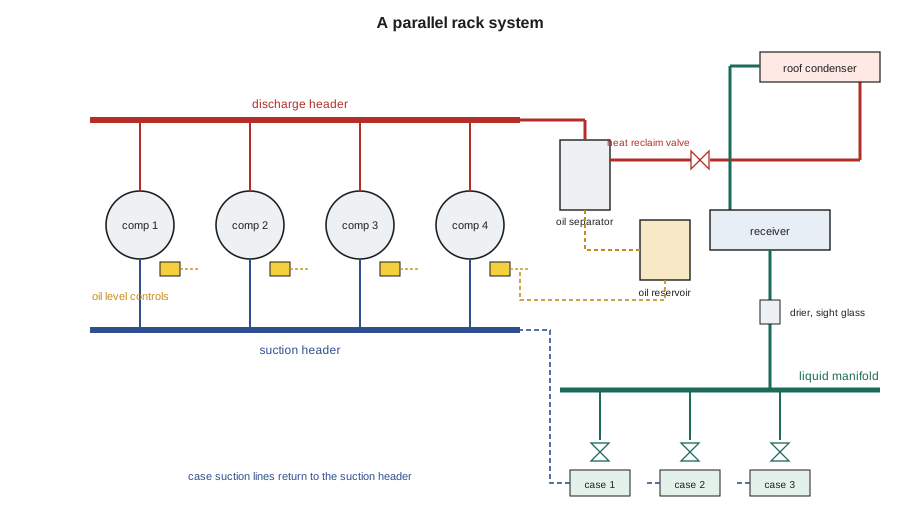
- Compressors: three to eight semi-hermetic reciprocating, scroll or, on large racks, screw compressors mounted on the frame and piped in parallel. Often one is variable speed or has capacity control.
- Suction header: a large pipe that collects suction gas from all the fixture circuits and feeds all the compressors. Some racks have more than one suction group at different pressures.
- Discharge header: collects the discharge gas from all the compressors and sends it to the oil separator and condenser.
- Oil separator and oil management: removes oil from the discharge gas and returns it to each compressor's crankcase under control.
- Condenser and heat reclaim: usually a remote air-cooled condenser on the roof, with valves that can send the discharge gas first to a heat reclaim coil in the store's air handler.
- Receiver: a tank that stores liquid refrigerant, absorbing the changes in charge distribution between summer and winter and between fixtures in and out of defrost.
- Liquid manifold: distributes liquid to the fixture circuits, after the liquid line drier, sight glass and often a subcooler.
- Circuit valves: solenoid valves, evaporator pressure regulators or electronic valves for each fixture circuit, and the defrost valves on racks with hot-gas defrost.
- Rack controller: an electronic controller that stages the compressors, controls the condenser and heat reclaim, schedules defrosts and raises alarms, as lesson 8 describes.
Sharing the load among compressors
The rack controller holds the suction pressure close to a setpoint by turning compressors on and off, or by changing the speed or capacity of one or more of them. With fixed-capacity compressors only, the rack's capacity moves in steps, and the suction pressure swings between the cut-in and cut-out of each stage. With a variable-speed lead compressor, the steps are smoothed out: the lead changes speed to fill in between the fixed stages, and the suction pressure stays steadier, which helps the fixtures hold temperature and saves energy.
There is a catch that Raj pointed out on the drawings. If the variable-speed compressor's range, from its minimum to its maximum capacity, is smaller than the capacity of one fixed compressor, there are loads the rack cannot match smoothly. When the load falls just below the point where a fixed compressor must stay on, the lead drops to its minimum speed and still has too much capacity, so the suction pulls down and the lead cycles on and off. The script below stages Harvest Lane's medium-temperature rack through a summer day's load, first with a smaller lead compressor and then with the larger one Nadia specified.
# Staging the medium-temperature rack: one variable-speed lead compressor and three fixed compressors
# Capacities at the rack's design suction and condensing temperatures (illustrative)
FIXED = 16.0                      # kW, each fixed compressor

def stage(load, vs_min, vs_max):
    """Fewest fixed compressors that let the lead carry the rest; flag loads the lead cannot match."""
    for n in range(4):
        rest = load - n * FIXED
        if rest <= vs_max:
            if rest >= vs_min or (n == 0 and rest > 0):
                return n, rest, 'matched' if rest >= vs_min else 'lead cycles'
            return n, vs_min, 'too much capacity, lead cycles'
    return 3, vs_max, 'short of capacity'

# a summer day's medium-temperature load, kW, at 2-hour steps from midnight (night covers on until 6 a.m.)
day = [34, 32, 31, 38, 47, 53, 57, 59, 58, 54, 46, 40]
for vs_min, vs_max in ((6.0, 18.0), (7.0, 24.0)):
    print(f"lead compressor {vs_min:.0f} to {vs_max:.0f} kW (range {vs_max - vs_min:.0f} kW, fixed step {FIXED:.0f} kW)")
    for k, load in enumerate(day):
        n, vs, note = stage(load, vs_min, vs_max)
        if note != 'matched' or k in (0, 7):
            print(f"  {2 * k:02d}:00 load {load:4.0f} kW: {n} fixed on, lead at {vs:4.1f} kW, {note}")
print(f" rack maximum {3 * FIXED + vs_max:.0f} kW for a design load of 60 kW")lead compressor 6 to 18 kW (range 12 kW, fixed step 16 kW) 00:00 load 34 kW: 1 fixed on, lead at 18.0 kW, matched 10:00 load 53 kW: 3 fixed on, lead at 6.0 kW, too much capacity, lead cycles 14:00 load 59 kW: 3 fixed on, lead at 11.0 kW, matched rack maximum 66 kW for a design load of 60 kW lead compressor 7 to 24 kW (range 17 kW, fixed step 16 kW) 00:00 load 34 kW: 1 fixed on, lead at 18.0 kW, matched 14:00 load 59 kW: 3 fixed on, lead at 11.0 kW, matched rack maximum 72 kW for a design load of 60 kW
With the smaller lead compressor, there are moments in the day when the load falls into the gap between stages, and the lead cycles. With the larger one, whose range is wider than the fixed step, every load from the lead's minimum to the rack's maximum can be matched. Theo noticed something else in the output: the rack has about 10 to 20 % more capacity than the design load, which covers a failed compressor on most days but not on the hottest afternoon. That is a normal design choice, and it is why the rack controller must alarm promptly when a compressor fails, so it can be repaired before a hot spell.
Racks also rotate their compressors so each one runs about the same number of hours, and limit how often each can start. When a compressor trips on a safety, the controller locks it out and brings on the next one. A rack running with one compressor locked out may hold temperature for days, and the only sign is an alarm that someone must act on.
Oil management
In a single compressor system, the oil that leaves the compressor with the discharge gas travels around the circuit and returns with the suction gas, as RAC-210 described. In a rack, several compressors share one suction header, and the oil does not divide itself evenly among them. One compressor can end up with too much oil and another with too little, which destroys its bearings. Racks therefore manage oil actively.
- An oil separator on the discharge header removes most of the oil from the discharge gas before it reaches the condenser and the fixtures.
- The separated oil drains to an oil reservoir, which is kept at a pressure a little above suction pressure by a differential check valve or a vent to the suction header.
- Each compressor has an oil level control, mechanical or electronic, that opens to feed oil from the reservoir when the crankcase level falls, and on many electronic controls alarms or stops the compressor if the level cannot be restored.
- Oil filters and, on many racks, sight glasses on the reservoir and each crankcase let the technician check levels.
Some oil still leaves with the discharge gas and travels to the fixtures, so the suction lines must be piped to return it, as RAC-210 described for risers and traps. A rack whose reservoir keeps running low is losing oil to somewhere in the system, often a case circuit with poor oil return or an evaporator that is flooded with liquid. A rack whose reservoir keeps filling is getting oil back faster than usual, which can happen after a defrost or when a circuit that has been logging oil finally clears it. Oil levels, oil additions and oil failure alarms belong in the service record.
The receiver and the charge
The receiver is the rack's reservoir of liquid refrigerant. Its level changes as the refrigerant moves around the system: in cold weather, when head pressure control floods part of the condenser with liquid, as RAC-210 described, the receiver level falls; in hot weather it rises. Defrosts, circuits switching on and off and heat reclaim also move refrigerant in and out of the receiver. A rack is charged so the receiver holds a working level, often 20 to 40 % full, under the conditions that leave it lowest, so the liquid line never runs short of liquid.
Because the receiver level reflects the total charge, it is also the best leak detector on the rack. Many racks have a liquid level sensor on the receiver that the controller logs. A slow, steady fall in the receiver level at similar weather and load conditions is a leak. Lesson 10 uses this. Technicians reading a receiver's level must compare it at similar conditions: the same rack at −10 °C (14 °F) outdoors in January and at 30 °C (86 °F) in July will show very different levels with the same charge.
Liquid line, subcooling and the fixture circuits
Liquid leaves the receiver, passes through a large replaceable-core drier and a sight glass, and enters the liquid manifold, which feeds each fixture circuit. On many racks, the liquid is subcooled before it leaves the machine room, by a mechanical subcooler on a low-temperature rack, by a heat exchanger with the medium-temperature rack, or by an ambient subcooler section in the condenser. Subcooling increases each kilogram's refrigerating effect, as RAC-110 showed, and protects the long liquid lines from flashing on their way to the fixtures.
Each fixture circuit has a liquid line solenoid or an electronic valve that the case controller opens and closes, the expansion device at the case, and a suction line back to the rack. Circuits are usually tagged at the manifold and in the rack controller with the fixtures they serve. Learning that tagging is the first thing a new technician does at a store, because when a case runs warm, the circuit's valves in the machine room are where the refrigerant side of the diagnosis begins.
The machine room
Rack systems are usually installed in a machine room, a dedicated space whose requirements come from refrigeration safety codes: CSA B52, which Ontario adopts through the TSSA. The rules depend on the refrigerant's safety group and the charge. For an A1 refrigerant such as R-448A in a machinery room, they typically include a refrigerant detector that alarms and starts mechanical ventilation, ventilation sized for the charge, doors that are tight-fitting and self-closing with signs, emergency shut-off controls outside the room, no open flames, and access limited to authorized people. The exact requirements are in the code edition the jurisdiction has adopted, and they apply to the installation as built.
A machine room is also a workplace with its own hazards. The rack's discharge lines are hot enough to burn, the compressors start automatically, and the electrical panel holds several hundred amperes. Refrigerant leaks in an enclosed room displace oxygen and, if the refrigerant reaches a flame or hot surface, decompose into toxic products, as RAC-120 explained. When the refrigerant detector alarms, leave the room and let the ventilation clear it before going back in with a personal monitor.
Common mistakes
MistakeAssuming a rack with a failed compressor is fine because the store is holding temperature.
InsteadAct on compressor failure alarms promptly; the spare capacity is needed on hot days.
MistakeSizing a variable-speed lead compressor smaller than one fixed step.
InsteadMake the lead's range wider than the largest fixed compressor so every load can be matched.
MistakeAdding oil to a rack without finding why the reservoir is low.
InsteadLook for poor oil return or a flooded circuit, and record every addition.
MistakeJudging the charge by one receiver reading.
InsteadCompare receiver levels at similar outdoor and load conditions.
MistakeEntering a machine room while its refrigerant alarm is sounding.
InsteadLeave, let the ventilation clear the room and re-enter with a personal monitor.
Summary and key terms
- A parallel rack serves many fixtures in one temperature class from compressors piped in parallel.
- Compressors stage or change speed to hold the suction pressure; a variable-speed lead should cover more than one fixed step.
- Oil separators, reservoirs and level controls share oil among the compressors.
- The receiver stores liquid, absorbs seasonal charge changes and reveals leaks over time.
- Liquid is dried, often subcooled, and distributed through a manifold to fixture circuits with their own valves.
- Machine rooms must meet the refrigeration safety code, including detection and ventilation.
- Suction header
- The common pipe that collects suction gas from all fixtures and feeds all a rack's compressors.
- Discharge header
- The common pipe that collects discharge gas from all a rack's compressors.
- Oil reservoir
- A tank that holds separated oil for distribution to a rack's compressors.
- Oil level control
- A device that feeds oil to a compressor's crankcase to keep its level correct.
- Receiver
- A tank that stores liquid refrigerant in the high side.
- Liquid manifold
- The header that distributes liquid to a rack's fixture circuits.
- Subcooler
- A heat exchanger that cools the liquid below its condensing temperature.
- Machinery room
- A room designed under the refrigeration safety code to house refrigerating machinery.
Practice problems
Work each problem on paper first, then reveal the answer to check.
Why can a rack be smaller than the sum of its fixtures' peak loads?
Show answer
The fixtures' peaks do not all happen at the same time.
A rack's oil reservoir keeps running low. Name two places the oil might be.
Show answer
Logged in a case circuit with poor oil return, or in a flooded evaporator; also check for a leak.
Why is the receiver level a useful leak indicator?
Show answer
It reflects the total charge; a steady fall at similar conditions shows refrigerant leaving.
What should happen when a machine room's refrigerant detector alarms?
Show answer
Ventilation starts, people leave, and re-entry is with a personal monitor after the room clears.
Lesson quiz · 5 questions
Score 60% or more to complete this lesson.
Create a free account to save your progress, take quizzes and earn a certificate.