
PLB-310 · Lesson 7 of 12 · 22 min
Expansion tanks, air elimination and system pressure
On her first service call with Grace, Maya watched a homeowner point at a puddle under a boiler. The relief valve had been dripping for weeks. Grace tapped the expansion tank: it rang hollow at the top and dull at the bottom, a sign that it was full of water. "The relief valve is not the problem," she said. "It is doing its job. The tank has failed, so every time the water heats up it has nowhere to expand, and the pressure climbs until the valve opens." This lesson explains why water expansion must be managed, how expansion tanks are sized and set, how a hydronic system is filled to the right pressure, and how air is removed and kept out.
Water expands when it is heated
Water's density falls as it warms. A closed system filled with 10 °C water and heated to 82 °C grows in volume by about 3 percent. In a system holding 330 litres, that is about 10 litres of extra water. Water barely compresses, so if that 10 litres has nowhere to go, the pressure rises very quickly, enough to open the relief valve in a few minutes of firing. The expansion tank gives the extra volume a place to go.
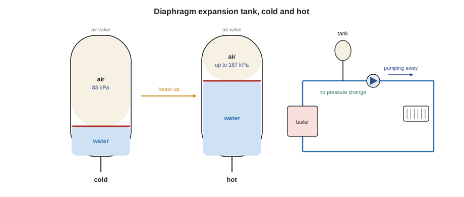
Modern expansion tanks are diaphragm or bladder tanks: a steel shell divided by a flexible membrane, with system water on one side and a cushion of compressed air or nitrogen on the other. As the water expands, it pushes against the membrane and compresses the air, and the pressure rises only gradually. Older systems used a plain steel compression tank, a tank hung near the ceiling with air in direct contact with the water. Those tanks work, but the air slowly dissolves into the water, so they must not be paired with automatic air vents, which would remove the air the tank depends on. Diaphragm tanks keep the air separate and are standard in new work.
Fill pressure and the static height
A hydronic system is filled to a pressure high enough to push water to the highest point with some pressure left over, so that air vents at the top work and the water near the top of the system does not drop below atmospheric pressure. Every metre of height takes about 9.8 kPa. A common rule is to fill to the static height times 9.8 kPa plus about 30 kPa at the top. The bungalow's highest radiator is about 5 m above the boiler, so it needs 5 × 9.8 + 30 ≈ 79 kPa; Grace set the fill at 83 kPa.
The expansion tank's air side must be precharged to the same pressure as the cold fill pressure at the tank's location before the tank is installed or with the system drained. If the precharge is lower than the fill pressure, the tank partly fills with water at start-up and has less room left for expansion. Tanks usually ship with a factory precharge of about 83 kPa, which suits many two-storey houses but must be checked with a tire gauge and adjusted for each job.
Tall buildings show how static height dominates. Kingsway's boilers are in the penthouse, so the system's highest point is close to the plant and the fill pressure at the expansion tank is modest. But the fan coils on the lowest floors sit about 45 m below, where the static pressure is over 440 kPa higher. Every valve, coil and fitting low in the building must be rated for that pressure, which is one reason engineers like to put plants at the top of tall buildings rather than in the basement.
Sizing an expansion tank
An expansion tank must be large enough to accept the expansion volume without the pressure rising past a safe maximum below the relief valve setting. The sizing equation uses absolute pressures, the gauge reading plus atmospheric pressure:
Here V_exp is the system volume times the expansion fraction, P_fill is the fill pressure and P_max is the highest pressure allowed at the tank, usually set about 20 kPa below the relief valve setting so the relief valve does not weep as the system approaches full temperature.
Worked problem
The bungalow's expansion tank
The bungalow system holds about 330 litres: 150 in the cast iron radiators, 150 in the buffer tank and 30 in the piping and boiler. It is filled at 10 °C to 83 kPa and can reach 82 °C when the boiler runs. The relief valve is set at 207 kPa. Size the tank.
Show solution
- Expansion fraction from 10 °C to 82 °C: about 3.0 percent. V_exp = 330 × 0.030 ≈ 10 L.
- Absolute fill pressure: 83 + 101 = 184 kPa. Maximum at the tank: 207 − 21 = 186 kPa gauge, 287 kPa absolute.
- V_tank = 10 ÷ (1 − 184 ÷ 287) = 10 ÷ 0.359 ≈ 28 L.
Answer: A tank of at least 28 litres is needed; Grace chose the next standard size up. The old system's tank had been about a third of that size, which helps explain the dripping relief valve she had seen on other houses with similar systems.
# Expansion tank size: V_tank = V_exp / (1 - Pfill_abs / Pmax_abs)
def density(t):        # water density in kg/m3, accurate from 0 to 100 C
    return 1000 * (1 - (t + 288.9414) / (508929.2 * (t + 68.12963)) * (t - 3.9863) ** 2)
def tank_l(volume_l, t_fill, t_max, p_fill_kpa, relief_kpa, margin_kpa=21, atm=101.3):
    v_exp = volume_l * (density(t_fill) / density(t_max) - 1)
    p1, p2 = p_fill_kpa + atm, relief_kpa - margin_kpa + atm
    return v_exp, v_exp / (1 - p1 / p2)

for t_max in (60, 71, 82):
    v_exp, v_tank = tank_l(330, 10, t_max, 83, 207)
print(f"max {t_max} C: expansion {v_exp:4.1f} L, tank at least {v_tank:4.1f} L")max 60 C: expansion 5.5 L, tank at least 15.5 L max 71 C: expansion 7.6 L, tank at least 21.2 L max 82 C: expansion 10.0 L, tank at least 27.8 L
The script shows how strongly the maximum temperature drives tank size. A heat pump system that never exceeds 60 °C needs a much smaller tank than the same system with a boiler that can reach 82 °C. Systems with glycol need larger tanks again, because glycol mixtures expand more than water; manufacturers publish correction factors.
Where the expansion tank connects
The point where the expansion tank connects to the system is the point of no pressure change. Because the tank holds a cushion of air at a set pressure, and the system's water volume does not change when the circulator starts, the pressure at the tank connection stays the same whether the circulator is running or not. Everywhere else, pressure rises or falls when the circulator starts: it rises downstream of the circulator outlet and falls upstream of its inlet.
That is why the circulator should pump away from the expansion tank. With the tank at the circulator's inlet, the circulator adds its head to the system pressure everywhere in the loop, which keeps air vents pushing air out and keeps pressure well above the boiling point. If the circulator pumps toward the tank instead, its inlet side drops below the fill pressure, and in a system with a low fill pressure the high points can fall below atmospheric pressure, drawing air in through vents and valve packing. The connection to the tank should be a short, unrestricted pipe with no valve that could be closed by accident, or a lockable service valve where the code and manufacturer allow one.
The fill connection
Makeup water enters through a pressure-reducing valve, often called a fill valve, set to the cold fill pressure. The plumbing code requires a backflow preventer on the connection from the potable water system, because boiler water can contain treatment chemicals and corrosion products. A dual check valve with an atmospheric port, or an assembly listed for the purpose under CSA B64, is common on plain water systems; systems with antifreeze or chemical treatment need a higher-protection device such as a reduced pressure principle assembly, as the Ontario code and the municipality require.
Many installers now leave the fill valve isolated after commissioning, or install a water meter on the fill line, so that a leak shows up as falling pressure or a meter reading instead of being silently made up with fresh water that brings in oxygen and minerals. A system that needs regular makeup has a leak, and the leak should be found.
Air in hydronic systems
Air causes noise, poor heat transfer, corrosion and circulator damage. It enters a system three ways: as pockets trapped during filling, as gases dissolved in the fill water, and through leaks or vents when part of the system falls below atmospheric pressure. Cold water holds more dissolved gas than hot water, so when fresh fill water is heated, the dissolved air comes out of solution as tiny bubbles, especially in the boiler where the water is hottest and the pressure is lowest relative to its temperature.
Air removal works in stages. During filling, the system is purged: each zone is flushed with fast-flowing water through purge valves until the water runs out with no bubbles. Manual bleed valves at high points release trapped pockets. In operation, a microbubble air separator, installed where the water is hottest and the pressure lowest, usually on the supply leaving the heat source, slows the water and gives the tiny bubbles a surface to collect on; they rise to an automatic float vent at the top and escape. Over the first few weeks, the separator removes the dissolved air until the water is nearly air-free.
Velocity also matters. Water moving at least about 0.6 m/s carries small bubbles along to the separator; slower water in large horizontal pipes lets them collect at high points. Automatic air vents are useful at high points that cannot be reached easily, but they must be installed upright and are a common source of small leaks, so many installers prefer a good central separator and manual vents at the emitters.
Dirt separators, often combined with air separators and fitted with magnets, catch magnetite and other particles. In retrofits like the bungalow, where decades of sludge come loose when a new system starts, a dirt separator protects the new heat exchangers and is cleaned out several times in the first season.
Filling and purging the bungalow, step by step
Maya filled the bungalow's new system herself, with Grace watching. First she checked the expansion tank's precharge with a tire gauge and adjusted it to the planned fill pressure while the tank was still empty of water. She closed the isolation valves on the boiler and the heat pump so that dirty flushing water could not reach their heat exchangers, and opened every thermostatic radiator valve fully, because a closed valve leaves an unpurged radiator.
She connected a hose from a purge valve on the return to a floor drain, opened the fill valve's fast-fill lever and let water rush through one circuit at a time until it ran clear and free of bubbles, then closed that circuit and moved to the next. Fast flow is the point: slow trickling leaves air in the high spots. With the circuits purged, she opened the heat source valves, purged them the same way, closed the purge valve and let the system come up to the fill pressure.
Next she bled each radiator at its manual vent, starting on the lowest floor and working up, and checked the pressure gauge after each one, topping up as the air came out. She started the circulator, listened for gurgling, and bled again after a few minutes of running. Grace had her record the fill pressure, the time and the water meter reading on the commissioning sheet. Over the next weeks the microbubble separator would remove the rest of the dissolved air, and the first follow-up visit would include another round of bleeding and a check that the pressure had settled where it should.
Common mistakes
MistakeInstalling an expansion tank without checking its precharge.
InsteadSet the precharge to the cold fill pressure at the tank before filling.
MistakeUsing automatic air vents with an old plain steel compression tank.
InsteadRemove the vents or replace the tank with a diaphragm tank.
MistakePumping toward the expansion tank.
InsteadConnect the tank at the circulator inlet so the circulator pumps away from it.
MistakeLeaving the fill valve open to quietly make up a leak.
InsteadFind and fix leaks; monitor makeup water with a meter or by closing the fill after commissioning.
MistakeTreating a dripping relief valve as the problem.
InsteadCheck the expansion tank and fill pressure first; the relief valve is reacting to high pressure.
Summary and key terms
- Water expands about 3 percent from 10 °C to 82 °C; the expansion tank absorbs that volume.
- Fill to the static height plus about 30 kPa at the top (9.8 kPa per metre).
- Precharge a diaphragm tank to the cold fill pressure at its location.
- Size the tank with absolute pressures so the maximum stays below the relief setting.
- The tank connection is the point of no pressure change; pump away from it.
- Backflow prevention on the fill connection must suit the system's water treatment.
- Purge during filling, then remove dissolved air with a microbubble separator at the hottest, lowest-pressure point.
- Expansion tank
- A tank that absorbs the increase in water volume as a closed system heats.
- Precharge
- The air pressure in an expansion tank before system water enters it.
- Fill pressure
- The cold pressure a system is filled to, set by its static height plus a margin.
- Point of no pressure change
- The expansion tank connection, where pressure stays the same whether the circulator runs or not.
- Microbubble air separator
- A device that collects and vents the tiny air bubbles released from heated water.
- Purging
- Flushing each circuit with fast-moving water to push trapped air out during filling.
- Pressure-reducing valve
- A valve that lowers incoming water pressure to the system fill pressure.
Practice problems
Work each problem on paper first, then reveal the answer to check.
A radiator is 8 m above the boiler. About what fill pressure is needed?
Show answer
8 × 9.8 + 30 ≈ 108 kPa.
Why must an expansion tank's precharge match the fill pressure?
Show answer
A lower precharge lets water partly fill the tank at start-up, leaving less room for expansion.
Why are absolute pressures used in tank sizing?
Show answer
The air cushion compresses according to absolute pressure.
Where is a microbubble air separator best located?
Show answer
Where the water is hottest and the pressure lowest, usually leaving the heat source.
What should a dripping relief valve make you check first?
Show answer
The expansion tank and the fill pressure.
Why is a reduced pressure principle assembly used on glycol systems?
Show answer
Glycol and treatment chemicals make the boiler water a higher hazard to the potable supply.
Lesson quiz · 5 questions
Score 60% or more to complete this lesson.
Create a free account to save your progress, take quizzes and earn a certificate.