
PLB-310 · Lesson 11 of 12 · 22 min
Balancing, commissioning and water treatment
The Kingsway Tower boiler plant had been running for a week when the property manager forwarded three complaints. Suites at the top of the north riser were cold, suites near the plant room on the east riser were too warm, and one tenant on the fourth floor could hear water rushing in the wall. Grace handed Maya a clipboard, a balancing meter and a set of riser drawings. "New systems are almost never balanced when they first start," she said. "Water takes the easy road. Our job is to make every path equally easy, then prove the system works and keep the water inside it in good shape." This lesson covers hydronic balancing, commissioning a new or rebuilt system, and treating the system water.
Why systems need balancing
Every branch of a hydronic system offers resistance to flow. Short branches close to the circulator offer little resistance and take more than their share of water; long branches far from it take less. Without correction, the near rooms overheat and the far rooms stay cold, even though the circulator and heat source are big enough. Balancing adds just enough resistance to the easy paths that every branch receives its design flow.
Balancing also protects the heat source and saves energy. Overflowing near branches return water that has barely cooled, which raises the return temperature and stops a condensing boiler condensing. Excess flow also causes velocity noise, like the rushing the fourth-floor tenant heard, and can erode copper fittings over time. A balanced system delivers design flow with the lowest pump speed that works.
Not every system needs much balancing. A small home system with a manifold and loops of similar length, or a properly designed reverse return layout, is nearly self-balancing. Larger systems with many branches of different lengths, such as Kingsway's risers, need it.
Balancing valves
A balancing valve is a valve with a calibrated setting scale and a pair of pressure test ports, one on each side of the valve's restriction. Connecting a balancing meter, which is a differential pressure gauge with a built-in valve database, to the ports shows the pressure drop across the valve. From the valve's setting and the measured pressure drop, the meter calculates the flow. Some valves have a fixed orifice or venturi for accurate measurement; others measure across the adjustable restriction itself.
The flow through a valve depends on its flow coefficient and the pressure drop across it. In metric units the coefficient is Kv, the flow in cubic metres per hour with a pressure drop of 1 bar (100 kPa). In US units it is Cv, the flow in US gallons per minute with a pressure drop of 1 psi. The two are related by Kv ≈ 0.865 Cv. Each setting on a balancing valve's scale has its own coefficient, listed in the manufacturer's table.
Worked problem
Reading the Kingsway riser valves
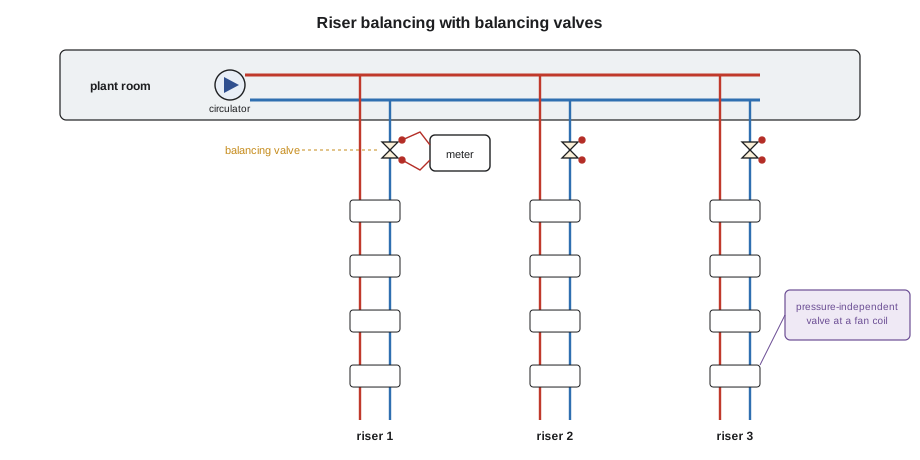
Each riser at Kingsway should carry 0.30 L/s. Maya reads the balancing valves at their current settings: riser 1 at Kv 3.2 with 18 kPa across it, riser 2 at Kv 2.5 with 12 kPa, and riser 3 at Kv 2.0 with 8 kPa. What is each riser's flow, and what setting would give design flow at the measured pressure drop?
Show solution
- Riser 1: Q = 3.2 × √(18 ÷ 100) = 3.2 × 0.424 = 1.36 m³/h = 0.38 L/s, too much.
- Riser 2: Q = 2.5 × √0.12 = 0.87 m³/h = 0.24 L/s, too little.
- Riser 3: Q = 2.0 × √0.08 = 0.57 m³/h = 0.16 L/s, far too little.
- Design flow 0.30 L/s is 1.08 m³/h. The coefficient needed at each measured drop is Kv = 1.08 ÷ √(Δp ÷ 100): about 2.5, 3.1 and 3.8.
Answer: Riser 1, the shortest, is stealing water from riser 3, the longest. Maya closes riser 1 down and opens risers 2 and 3. Because every change shifts the pressure across the other valves, she will read them all again afterward and repeat until each is within about 10 percent of design.
# Balancing valve flow from Kv setting and measured pressure drop
from math import sqrt

design = 0.30                                  # L/s per riser
risers = [("Riser 1", 3.2, 18), ("Riser 2", 2.5, 12), ("Riser 3", 2.0, 8)]   # name, Kv, dp kPa

for name, kv, dp in risers:
    q = kv * sqrt(dp / 100) / 3.6              # m3/h -> L/s
    kv_need = design * 3.6 / sqrt(dp / 100)
print(f"{name}: {q:.2f} L/s ({q / design * 100:3.0f}% of design), set Kv about {kv_need:.1f}")Riser 1: 0.38 L/s (126% of design), set Kv about 2.5 Riser 2: 0.24 L/s ( 80% of design), set Kv about 3.1 Riser 3: 0.16 L/s ( 52% of design), set Kv about 3.8
Balancing methods
The simplest approach, often used on small systems, is temperature balancing: run the system, measure the supply and return temperature of each branch, and close down the branches with a small temperature difference until all branches show close to the design ΔT. It needs only a surface thermometer, but it is slow, because temperatures take time to settle, and it works only when the system is under load.
The proportional method is the standard for larger systems. The technician measures every branch, finds the one with the lowest percentage of design flow, the index branch, and leaves its valve fully open. Every other branch is adjusted so that its percentage matches the index branch. When all branches are proportionally equal, the main balancing valve or the circulator speed is adjusted to bring the whole system up to design, and every branch rises together. Kingsway's risers are balanced this way, then the branches on each floor.
Many new systems avoid manual balancing altogether by using pressure-independent control valves at each terminal. A pressure-independent valve has a built-in regulator that holds a constant pressure across its control part, so the flow at a given setting stays the same no matter how the pressure in the system changes. The designer sets each valve to its design flow, and opening or closing other valves does not disturb it. They cost more than ordinary valves but save balancing time and keep the system balanced as zones open and close.
Every balancing job ends with a balancing report that lists each valve, its final setting, the measured pressure drop and the resulting flow. The report goes into the building's records. Years later, when a tenant complains or a valve is replaced, the service plumber can reset the valve to its recorded setting instead of starting over.
Filling, flushing and purging
Before a new system is balanced, it has to be clean, full and free of air. Flushing removes flux, cutting oil, solder balls and debris from installation. A new system is flushed with clean water, often with a cleaning chemical approved for the system's materials, through each zone in turn, until the water runs clear. An existing system being connected to a new boiler is flushed even more carefully, because old systems carry sludge and magnetite that can foul a modern heat exchanger in weeks. A dirt separator and magnetic filter on the return to the new heat source catch what flushing misses.
Purging pushes the air out. With the boiler isolated, water from the fill is directed through one zone at a time and out a purge valve to a hose, until no more air bubbles come out. Once each zone runs solid water, the purge valve is closed and the next zone is purged. The circulator is then started and automatic air vents and the air separator remove the dissolved air that remains over the next days.
The system is pressure tested before insulation and finishes hide the piping, as the code and the system specification require, then filled to its cold fill pressure. Remember the fill rule from Lesson 7: the static pressure at the top of the system plus a margin.
Commissioning a hydronic system
Commissioning is the documented process of proving that a system has been installed correctly and performs as designed. For a home system it may be a one-page checklist; for Kingsway it is a binder signed by the contractor, the engineer and the owner's representative. Either way, it follows the same sequence.
| Step | What is checked |
|---|---|
| Visual inspection | Piping, supports, valves, vents, relief discharge, labels, clearances |
| Cleaning and filling | Flushed, filled with treated water, purged, fill pressure recorded |
| Expansion and relief | Tank precharge matches fill pressure; relief valve rating and discharge correct |
| Heat source | Start-up to the manufacturer's instructions; combustion test or heat pump readings recorded |
| Circulators | Rotation, control mode and speed setting recorded |
| Controls | Every thermostat starts its zone; reset curve, warm weather shutdown and DHW priority set |
| Balancing | Each branch at design flow; balancing report complete |
| Performance | Supply, return and ΔT recorded under load; rooms reach set temperature |
| Handover | Owner shown controls and maintenance; manuals and records left on site |
Grace insists on recording numbers, not ticks. "Checked" tells the next technician nothing; "fill 120 kPa, tank precharge 120 kPa, relief 210 kPa" tells them exactly how the system left the installer's hands. A commissioning sheet with real readings is also the best tool for future troubleshooting, as Lesson 12 shows.
Water quality and treatment
Water inside a closed hydronic system is not changed often, so it can be managed precisely. Problems come from three sources: dissolved oxygen, which corrodes steel and cast iron; hardness minerals, which form scale on hot heat exchanger surfaces; and the wrong pH, which attacks metals. A tight system with no leaks takes in very little new water, so once the water is right, it stays right.
Scale is the most serious threat to modern boilers. A thin layer of scale on a compact heat exchanger insulates it, raising metal temperatures and cutting efficiency, and can crack the exchanger. Systems filled with hard water are therefore filled with softened or demineralized water, or treated to keep the minerals in solution. Each top-up of fresh water brings in more minerals, which is another reason to find and fix leaks rather than keep refilling.
Corrosion control relies on keeping oxygen out, holding pH in the right range and adding an inhibitor that films metal surfaces. Most mixed-metal systems with steel and copper run best between about pH 8.2 and 9.5. Heat exchangers made of aluminium need a lower, narrower range, often up to about 8.5, set by the manufacturer. Because limits vary, the boiler's installation manual is the authority on water quality, and failing to follow it can void the warranty.
Testing is simple: a sample from a drain valve is checked for pH, hardness, total dissolved solids and inhibitor level using test strips or a meter, and the results are recorded on the commissioning sheet. Kingsway's maintenance contract calls for testing every year. Dark, cloudy water, black magnetite in the filter or a rising need for top-ups are signs of trouble.
Glycol for freeze protection
Systems with piping in places that could freeze, such as a garage, snowmelt slabs, air handler coils with outdoor air, or the outdoor unit circuit of a monobloc heat pump, are filled with an antifreeze solution. Propylene glycol is used for heating systems because it has low toxicity; ethylene glycol is more toxic and is not used where it could reach potable water. Heating glycol is always the inhibited type made for hydronic systems, never automotive antifreeze, which contains additives that cause sludge.
Glycol is mixed to the lowest temperature the piping could reach, often 30 to 40 percent by volume, which protects to roughly −13 to −21 °C. Glycol has a lower specific heat and a higher viscosity than water, so the same heat needs more flow and more pumping head. Designers typically raise the flow by 10 to 20 percent and check the circulator. The concentration is checked with a refractometer, and the inhibitor in glycol wears out over the years, so glycol systems are tested annually.
In the bungalow, the heat pump is a monobloc type, with its refrigerant circuit and water heat exchanger outside. Its water lines are filled with a propylene glycol mix. A plate heat exchanger separates that loop from the indoor radiators, which run on treated water, so the whole house does not need glycol. Grace labelled the glycol loop and recorded its concentration on the commissioning sheet.
Common mistakes
MistakeStarting a new boiler on an unflushed old system.
InsteadFlush thoroughly and install a dirt separator and magnetic filter.
MistakeBalancing by feel or by guesswork.
InsteadMeasure flow at balancing valves and record final settings.
MistakeAdjusting one valve and assuming the others stay put.
InsteadRead all branches again after each round of adjustments.
MistakeFilling with hard water and topping up for every leak.
InsteadFill with treated water and fix leaks instead of refilling.
MistakeUsing automotive antifreeze in a heating system.
InsteadUse inhibited propylene glycol made for hydronics, tested yearly.
Summary and key terms
- Balancing gives every branch its design flow, protecting comfort, condensing and quiet operation.
- Balancing valves are read with a meter: Q = Kv √(Δp/100) or Q = Cv √Δp.
- The proportional method balances branches relative to the index branch, then raises the whole system.
- Pressure-independent control valves hold their set flow as system pressures change.
- Systems are flushed, filled, purged and pressure tested before balancing.
- Commissioning records real readings: fill, precharge, relief, settings, flows and temperatures.
- Water treatment controls oxygen, scale and pH; glycol protects piping that could freeze.
- Balancing valve
- A valve with a calibrated setting and test ports used to measure and set flow.
- Flow coefficient
- The flow through a valve at a standard pressure drop: Kv in metric, Cv in US units.
- Index branch
- The branch with the lowest percentage of design flow, left fully open in proportional balancing.
- Pressure-independent control valve
- A valve that holds its set flow regardless of changes in system pressure.
- Commissioning
- The documented process of proving a system is installed correctly and performs as designed.
- Inhibitor
- A chemical added to system water to protect metals from corrosion.
- Refractometer
- An instrument that measures glycol concentration from a few drops of fluid.
Practice problems
Work each problem on paper first, then reveal the answer to check.
A balancing valve at Kv 4.0 shows 25 kPa. What is the flow in L/s?
Show answer
4.0 × √0.25 = 2.0 m³/h, about 0.56 L/s.
In proportional balancing, which valve is left fully open?
Show answer
The valve on the index branch, the one with the lowest percentage of design flow.
Why does excess flow in near branches hurt a condensing boiler?
Show answer
It returns warm water, raising return temperature and stopping condensation.
What three things does water treatment control?
Show answer
Dissolved oxygen, scale-forming hardness and pH.
Why is propylene glycol used in heating systems?
Show answer
It has low toxicity compared with ethylene glycol.
Why should a commissioning sheet record numbers rather than ticks?
Show answer
Numbers show exactly how the system was set and help future troubleshooting.
Lesson quiz · 5 questions
Score 60% or more to complete this lesson.
Create a free account to save your progress, take quizzes and earn a certificate.