
PLB-130 · Lesson 8 of 12 · 24 min
Booster pumps and pressure zones in tall buildings
The booster pump package arrived at Kingsway on a flatbed truck: three stainless steel pumps on a common steel base, with suction and discharge headers, check valves, a control panel and a small pressure tank, all factory assembled and tested. It took a forklift, a chain hoist and most of a morning to set it on its housekeeping pad in the lower parking level mechanical room. Maya helped Luis level it and line up the headers with the copper mains. As they worked, Luis explained what the package does and why a building like Kingsway cannot run without it.
Lesson 1 showed that the city's pressure cannot lift water to Kingsway's upper floors with enough left over for the fixtures. Lesson 3 showed that pressure high enough for the top floors would be too high for the bottom floors. This lesson brings those two problems together. It explains how booster pumps raise pressure, how they are controlled, how they are sized, and how tall buildings are divided into pressure zones so that every floor gets pressure inside the limits.
When a building needs boosting
A building needs booster pumps when the utility's minimum pressure, after subtracting the height to the top fixture, the losses through the meter and backflow preventer, the friction in the piping and the minimum flowing pressure at the fixture, comes out below zero. As a rough rule, low-rise buildings on a good city main rarely need boosting; buildings of six or more storeys often do; and towers always do. The exact answer depends on the street pressure, which varies from city to city and even from street to street.
Boosting is also needed when the utility's pressure is good most of the time but drops on hot summer evenings, or when the city plans to lower pressure in an area. The engineer designs with the lowest pressure the utility will guarantee, not the pressure measured on a quiet morning. Hamilton, like most utilities, will report the design pressures for a given address on request.
How a booster package works
Modern booster packages use two or more centrifugal pumps driven by variable-frequency drives, usually called VFDs. A pressure sensor on the discharge header measures the building's pressure, and the controller speeds the pumps up or slows them down to hold a constant discharge pressure. When demand is light, one pump runs slowly. As demand rises, it speeds up, and when it reaches full speed the controller starts a second pump. When demand falls, pumps slow and stop in reverse order.
- Multiple pumps provide redundancy and efficiency. A common arrangement is two duty pumps that together meet peak demand, plus a standby pump that takes over if one fails. The controller rotates which pump leads so they wear evenly.
- Check valves on each pump's discharge stop water flowing backward through an idle pump.
- Isolation valves on each pump let one be removed for repair while the others keep running.
- A small diaphragm pressure tank on the discharge header supplies tiny flows, such as a dripping faucet or a toilet refilling at night, so the pumps can shut off instead of running constantly at no flow.
- A suction pressure sensor or switch stops the pumps if the city pressure falls too low, so the booster does not pull a vacuum on the city main or run dry.
- A bypass with a check valve lets city pressure feed the building directly if all the pumps stop, so the lower floors still get water.
Older buildings may have constant-speed boosters, in which pumps run at full speed and a pressure-reducing valve on each pump holds the discharge pressure, or hydropneumatic systems with large pressure tanks that let pumps cycle on and off. Some very old buildings, and many tall buildings around the world, use roof tanks: pumps fill a tank on the roof, and the tank feeds the building by gravity. Each system has its place, but VFD packages are now the usual choice for new buildings because they save energy and hold pressure steady.
Sizing the booster: flow and head
A booster pump package is sized by two numbers: the flow it must deliver and the pressure it must add, called the boost or head.
- Flow is the peak demand of everything the booster serves, worked out from fixture units and continuous flows as in Lesson 5.
- Head is the difference between the discharge pressure needed and the lowest suction pressure the booster will see at that flow.
The discharge pressure is set by the pressure budget: enough to lift water to the top fixture, overcome friction in the mains and risers, pass through suite devices and still leave the minimum flowing pressure at the fixture. The suction pressure is the city's minimum residual pressure at peak flow, corrected for the height of the meter room, minus the losses through the service, meter, strainer and backflow preventer.
Worked problem
Sizing Kingsway's booster
The booster serves the whole building at a peak of 15.4 L/s. The required discharge pressure is 690 kPa. At peak flow the minimum suction pressure, after the meter and backflow preventer, is 350 kPa. Find the boost, and estimate the power if the pumps are 65 percent efficient.
Show solution
- Boost: \(690 - 350 = 340\) kPa, which is \(340 / 9.81 \approx 34.7\) m of head.
- Hydraulic power: \(P = \rho g Q H = 1000 \times 9.81 \times 0.0154 \times 34.7 \approx 5\,240\) W.
- Shaft power: \(5\,240 / 0.65 \approx 8\,060\) W, about 8.1 kW.
- With two duty pumps sharing the peak, each must deliver about 7.7 L/s at 34.7 m.
Answer: A boost of about 340 kPa and about 8 kW of pump power at peak, split between two duty pumps with a third on standby.
Most of the time, the building uses far less than the peak, and the VFDs let the pumps slow down and use much less power. That is the main energy advantage of variable-speed boosters: power falls steeply as speed falls, so a pump running at half speed uses only a small fraction of its full-speed power.
# Booster head and power, and how power falls at part load (SI units)
RHO_G = 9.81          # kN per m^3 for water
q_peak = 15.4         # L/s
p_dis, p_suc = 690, 350
eff = 0.65

head_m = (p_dis - p_suc) / 9.81
power_kw = RHO_G * (q_peak / 1000) * head_m / eff
print(f"boost {p_dis - p_suc} kPa = {head_m:.1f} m; power at peak {power_kw:.1f} kW")

# With constant discharge pressure the head stays about the same,
# so power falls roughly in proportion to flow at part load.
for frac in (1.0, 0.6, 0.3, 0.1):
    q = q_peak * frac
    p = RHO_G * (q / 1000) * head_m / eff
print(f"{frac:4.0%} of peak: {q:5.2f} L/s about {p:4.1f} kW")boost 340 kPa = 34.7 m; power at peak 8.1 kW 100% of peak: 15.40 L/s about 8.1 kW 60% of peak: 9.24 L/s about 4.8 kW 30% of peak: 4.62 L/s about 2.4 kW 10% of peak: 1.54 L/s about 0.8 kW
The program shows power falling with flow. In practice the savings are even larger at very low flows, because the pumps shut off completely and the pressure tank carries the small draws.
Why tall buildings are zoned
Water pressure changes by the same amount for every floor climbed, whether the source is the city or a booster. In a 12-storey building, the difference between the pressure at the bottom and the top of a riser is around 360 kPa or 52 psi from height alone. If the top floor gets the minimum it needs, the bottom floor of the same riser gets that minimum plus the whole column of water above it. In a tall enough building, that sum exceeds the code maximum.
The solution is to divide the building into pressure zones, each spanning a limited number of floors, so that the pressure range within each zone stays between the minimum the top of the zone needs and the maximum the bottom of the zone can tolerate. The maximum height of a zone is roughly the difference between those two pressures divided by the pressure per floor.
For example, if the top of a zone needs at least about 280 kPa static and the bottom may not exceed 550 kPa, the zone can span about \((550 - 280) / 9.81 \approx 27\) m, or about nine storeys at 3 m each. Taller buildings need more zones.
Ways to make zones
There are three common ways to create pressure zones, and large buildings often combine them.
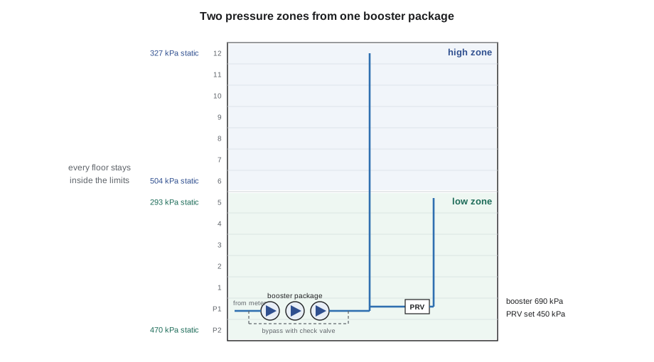
- PRV zones. One booster delivers enough pressure for the top zone, and pressure-reducing valve stations step the pressure down for each lower zone. This is simple and uses one booster package, but the pump lifts all the water to the top-zone pressure even though much of it is then throttled down, which wastes some energy. Kingsway uses this arrangement.
- Separate boosters. Each zone has its own booster package set to the pressure that zone needs. This saves energy in very tall buildings, where the lower zones may need little or no boosting, but costs more in equipment and space.
- Intermediate tanks or pump stations. Very tall towers may pump to tanks or pump rooms on intermediate mechanical floors, which then feed or boost the zones above and below them. This limits the pressure any one pipe or pump has to handle.
Whatever the method, each zone needs its own isolation valves so it can be shut down without affecting the others, and each PRV or booster needs the protection discussed in Lesson 3: gauges, strainers, relief where needed and access for service.
Worked problem
Pressures at the ends of each Kingsway zone
The booster delivers 690 kPa at the lower parking level. Floor 6 fixtures are 19 m above the booster and floor 12 fixtures are 37 m above it. The low-zone PRV delivers 450 kPa; floor 5 fixtures are 16 m above it and the lowest parking fixture is 2 m below it. Check the static pressures at the ends of each zone.
Show solution
- High zone bottom (floor 6): \(690 - 19 \times 9.81 = 690 - 186 = 504\) kPa.
- High zone top (floor 12): \(690 - 37 \times 9.81 = 690 - 363 = 327\) kPa.
- Low zone top (floor 5): \(450 - 16 \times 9.81 = 293\) kPa.
- Low zone bottom (lower parking): \(450 + 2 \times 9.81 = 470\) kPa.
- All four are between about 280 and 550 kPa.
Answer: Both zones stay inside the limits at both ends, which is exactly what the zoning was designed to do.
Installing and starting a booster
Booster packages are heavy, vibrating equipment connected to rigid copper mains. Good installation keeps vibration and noise out of the building and makes the package easy to service.
- Set the package on a concrete housekeeping pad, level it, and anchor it as the manufacturer specifies. Vibration isolators may be required, especially near occupied spaces.
- Use flexible connectors on the suction and discharge headers so the pumps' vibration and the pipes' thermal movement do not stress the connections. Support the piping independently so its weight does not hang on the package.
- Provide clearances for removing a pump or motor, and a floor drain nearby for draining and seal leakage.
- Wire the controls, the suction pressure switch and any alarm outputs to the building automation system so the operator knows when a pump fails or suction pressure is low.
- Start-up is usually done by the manufacturer's technician with the plumber present: venting air from the pumps, checking rotation, setting the discharge pressure, testing each pump, the alternation, the low suction cutout and the bypass.
Power failure deserves a thought. When the power goes out, the booster stops and the upper floors lose water pressure, while the lower floors may still get city pressure through the bypass. Many tall buildings connect the booster to emergency or standby power, and the engineer decides based on the building's needs and the electrical code.
Common mistakes
MistakeSizing a booster for the city's typical pressure instead of its guaranteed minimum.
InsteadUse the lowest pressure the utility will guarantee at peak flow.
MistakeLeaving out the suction pressure cutout.
InsteadInstall it so the booster cannot pull a vacuum on the city main or run dry.
MistakeBolting pump headers rigidly to the building's mains.
InsteadUse flexible connectors and support the piping independently.
MistakeMaking a single zone too tall.
InsteadLimit each zone so its top gets the minimum pressure and its bottom stays under the maximum.
MistakeForgetting the bypass around the pumps.
InsteadProvide a bypass with a check valve so city pressure can still feed the building if the pumps stop.
Summary and key terms
- Booster pumps raise pressure when the city's minimum pressure cannot serve the upper floors.
- Modern packages use several pumps on variable-frequency drives with check valves, isolation valves, a small pressure tank, a suction cutout and a bypass.
- A booster is sized for the peak demand it serves and the boost from the minimum suction pressure to the required discharge pressure.
- Variable speed saves energy because most of the time demand is far below the peak.
- Tall buildings are divided into zones so that pressure at every floor stays between the minimum and the code maximum.
- Zones can be made with PRV stations, separate boosters or intermediate tanks and pump rooms.
- Booster pump
- A pump that raises the pressure of the incoming water supply to serve a building.
- Variable-frequency drive
- An electronic controller that changes a motor's speed to match demand.
- Boost
- The pressure a booster adds, from its suction pressure to its discharge pressure.
- Suction pressure cutout
- A control that stops a booster when the incoming pressure falls too low.
- Duty and standby pumps
- Pumps that run to meet demand, and a spare pump that takes over if one fails.
- Roof tank system
- A system in which pumps fill a tank at the top of a building that feeds the floors by gravity.
Practice problems
Work each problem on paper first, then reveal the answer to check.
Why does a booster package include a small pressure tank?
Show answer
So small flows at night can be met from the tank and the pumps can shut off.
A booster's suction is 300 kPa at peak and it must discharge 700 kPa. What is the boost in metres of head?
Show answer
400 kPa divided by 9.81, about 41 m.
Why are most new boosters variable speed?
Show answer
They hold pressure steady and save energy because demand is usually far below peak.
Roughly how tall can a zone be if the top needs 280 kPa and the bottom may not exceed 550 kPa?
Show answer
About 27 m, or nine storeys at 3 m.
Name the three ways to create pressure zones.
Show answer
PRV stations, separate boosters for each zone, and intermediate tanks or pump rooms.
What happens on the upper floors if the booster loses power?
Show answer
They lose pressure; lower floors may still get city pressure through the bypass.
Lesson quiz · 5 questions
Score 60% or more to complete this lesson.
Create a free account to save your progress, take quizzes and earn a certificate.