
PLB-130 · Lesson 6 of 12 · 23 min
Sizing supply piping
With the demand worked out, Luis sat Maya down with a calculator, the riser diagram and a friction chart. He wanted her to size one path through the high zone, from the booster pumps to the farthest suite on the twelfth floor, the way an engineer would. She would not be designing systems as an apprentice, he said, but a plumber who understands how pipes were sized knows which changes on site are harmless and which ones will leave a shower dribbling on the top floor.
This lesson puts Lessons 3, 4 and 5 together. Sizing a water system means choosing, for every length of pipe, the smallest size that carries its peak demand without losing too much pressure and without moving the water too fast. The method used here, sometimes called the pressure budget or friction rate method, is the basis of the sizing appendices in the model codes and of most engineers' calculations.
The four limits on every pipe
Every pipe in a water system must satisfy four limits at once:
- It must carry its peak demand, worked out from the fixture units of everything downstream plus any continuous flows.
- It must not lose so much pressure that the farthest fixture falls below its minimum flowing pressure.
It must keep velocity below the limit: commonly about 2.4 m/s for cold water and 1.5 m/s for hot water in copper.
- It must be at least the minimum size the code sets for that kind of pipe or fixture connection.
The first limit sets how much water the pipe must move. The other three decide how big it has to be to move it. In small buildings with plenty of pressure, velocity usually decides the size. In tall buildings or long runs where pressure is tight, friction usually decides it.
Step 1: the pressure budget
Start with the pressure available at the source and subtract everything that is not friction in the piping. What is left is the pressure you can afford to lose to friction along the most demanding path, which is usually the one to the highest and farthest fixture.
- Start: the minimum residual pressure available at the source while water flows, such as the city main's low pressure or the booster's discharge setting.
- Subtract the height from the source to the highest fixture.
- Subtract the losses through devices in the path: meter, backflow preventer, strainer, pressure-reducing valve, water heater, submeters.
- Subtract the minimum flowing pressure needed at the critical fixture.
- What remains is the pressure available for friction in pipe and fittings.
Worked problem
The pressure budget for Kingsway's high zone
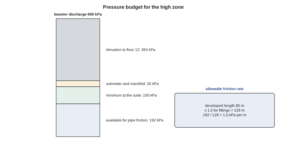
The booster delivers 690 kPa. The highest suite manifold is 37 m above the booster. The suite submeter and manifold take 35 kPa at peak suite flow, and the engineer requires 100 kPa flowing at the manifold. How much pressure is available for friction in the mains and riser?
Show solution
- Elevation: \(37 \times 9.81 \approx 363\) kPa.
- Devices: 35 kPa.
- Minimum at the manifold: 100 kPa.
- Available for friction: \(690 - 363 - 35 - 100 = 192\) kPa.
Answer: 192 kPa can be lost to friction in the pipe and fittings from the booster to the top suite.
Step 2: the allowable friction rate
Measure the developed length of the critical path, the actual length of pipe along the route the water travels from the source to the critical fixture, including risers. Add an allowance for fittings, either by counting equivalent lengths or by adding a percentage, often 50 percent for early sizing. Divide the pressure available for friction by this total length. The result is the allowable friction rate: the average loss per unit length that the path can afford.
For Kingsway's high zone, the critical path from the booster to the farthest twelfth-floor manifold is 85 m. With a 50 percent fittings allowance it counts as about 128 m. The allowable friction rate is therefore \(192 / 128 = 1.5\) kPa per metre.
Using one average friction rate for the whole path is a simplification. In practice, engineers often let the large mains, which are expensive, run at a lower rate and accept a higher rate in the short, small branches near the end. What matters is that the total loss along the path fits the budget.
Step 3: size each segment
Divide the path into segments wherever the demand changes, usually at each branch or riser takeoff. For each segment, add up the fixture units downstream, convert them to demand, and choose the smallest pipe that carries that demand at or below the allowable friction rate and below the velocity limit. Then check the minimum size rules. Finally, add up the actual losses segment by segment and confirm the total is within the budget.
The program below does exactly that for Kingsway's high-zone cold water path. It uses the illustrative demand curve from Lesson 5, the Hazen-Williams formula from Lesson 4 and type L copper sizes. Read the output line by line: it shows the size chosen for each segment, the reason, the velocity, and the running total of pressure lost.
# Sizing the high-zone cold water path by the friction rate method (SI units)
import math

SIZES = [("19", 19.9), ("25", 26.0), ("32", 32.1), ("38", 38.2),
         ("50", 50.4), ("65", 62.6), ("75", 74.8), ("100", 99.2)]   # name, ID mm
RATE = 1.5          # allowable friction, kPa per m (from the pressure budget)
VMAX = 2.4          # m/s for cold water
BUDGET = 192        # kPa available for friction
FITTINGS = 1.5      # multiply measured length to allow for fittings

def demand(fu):                     # illustrative curve from Lesson 5
    return 0.098 * fu ** 0.71

def loss(q, d_mm, c=140):           # kPa per m, Hazen-Williams
    q, d = q / 1000, d_mm / 1000
    return 9.81 * 10.67 * q ** 1.852 / (c ** 1.852 * d ** 4.87)

def vel(q, d_mm):
    return (q / 1000) / (math.pi * (d_mm / 1000) ** 2 / 4)

segments = [("cold main, booster to shaft C", 518, 25),
            ("cold main, shaft C to shaft E", 296, 20),
            ("riser E, P1 to floor 6", 51.8, 22),
            ("riser E, floor 6 to floor 9", 29.6, 9),
            ("riser E, floor 9 to floor 12", 7.4, 9)]
total = 0
for name, fu, length in segments:
    q = demand(fu)
    for size, d in SIZES:
        if loss(q, d) <= RATE and vel(q, d) <= VMAX:
            break
    seg = loss(q, d) * length * FITTINGS
    total += seg
    print(f"{name:30s} {fu:5.1f} FU {q:5.2f} L/s -> {size:>3s} mm"
          f"  {vel(q, d):4.2f} m/s  {seg:5.1f} kPa  running {total:5.1f}")
print(f"total friction {total:.0f} kPa of {BUDGET} kPa available:",
"ok" if total <= BUDGET else "over budget")cold main, booster to shaft C 518.0 FU 8.29 L/s -> 75 mm 1.89 m/s 17.7 kPa running 17.7 cold main, shaft C to shaft E 296.0 FU 5.57 L/s -> 65 mm 1.81 m/s 16.2 kPa running 33.9 riser E, P1 to floor 6 51.8 FU 1.62 L/s -> 32 mm 2.00 m/s 46.5 kPa running 80.3 riser E, floor 6 to floor 9 29.6 FU 1.09 L/s -> 32 mm 1.34 m/s 9.1 kPa running 89.4 riser E, floor 9 to floor 12 7.4 FU 0.41 L/s -> 19 mm 1.30 m/s 15.1 kPa running 104.5 total friction 105 kPa of 192 kPa available: ok
The total comes in under the budget, so this path works, and the leftover pressure is margin. The fixture unit loads use the cold values from Lesson 5: 7.4 cold fixture units per suite, 7 suites on each riser and 70 suites in the high zone. The hot water risers and mains are sized the same way using the hot values and the lower velocity limit for hot water.
Look at which limit decided each size. In the mains and the lower riser, friction and velocity decide the size together. In the top section of the riser, the flow is so small that the smallest size in the list passes easily. That is a typical pattern: large pipes near the source are sized by friction and velocity, and small pipes near the fixtures are sized by the minimum size rules.
Minimum sizes
Codes set minimum sizes so that small pipes do not starve fixtures even when the calculation says a tiny pipe would do. They also set a minimum size for the water service and for the pipe that feeds each fixture.
| Fixture supply (course practice) | Minimum size |
|---|---|
| Lavatory | 10 mm |
| Water closet, flush tank | 10 mm |
| Bathtub or shower | 12 mm |
| Kitchen sink | 12 mm |
| Dishwasher | 12 mm |
| Clothes washer | 12 mm |
| Hose bibb | 12 mm |
| Water closet, flush valve | 25 mm |
The Ontario Building Code and the National Plumbing Code also set a minimum size for the water service, and many cities set a larger minimum in their own standards. Kingsway's service is far above any minimum because of the building's demand.
Sizing suite piping with manifolds
Kingsway's suites use a home-run manifold system: a manifold in the laundry closet with a separate PEX line to each fixture. Each line carries only one fixture's flow, so it is sized for that fixture alone, with no diversity. The manifold and its supply are sized for the suite's total fixture units.
PEX has a smaller inside diameter than copper of the same nominal size, because it is sized by outside diameter and has a thicker wall. Its friction loss per metre is therefore higher, which matters on long home-run lines. The manufacturer publishes friction data for each size. On Kingsway, the longest home-run, to the ensuite shower, is about 14 m, which the engineer checked against the manifold pressure and the shower valve's minimum.
Worked problem
Checking a long home-run line
A 12 mm PEX line (inside diameter about 12 mm) runs 14 m from the manifold to a shower and carries 0.15 L/s. Allowing 30 percent for fittings, what is the friction loss? Use C = 150 for PEX.
Show solution
- Head loss per metre: \(h_f = 10.67 \times 0.00015^{1.852} / (150^{1.852} \times 0.012^{4.87})\).
- Working the powers: \(0.00015^{1.852} \approx 8.3 \times 10^{-8}\), \(150^{1.852} \approx 10\,720\), \(0.012^{4.87} \approx 4.4 \times 10^{-10}\).
- So \(h_f \approx 10.67 \times 8.3 \times 10^{-8} / (10\,720 \times 4.4 \times 10^{-10}) \approx 0.19\) m per m, or about 1.8 kPa per m.
- Loss: \(1.8 \times 14 \times 1.3 \approx 33\) kPa.
Answer: About 33 kPa. With 100 kPa at the manifold, about 67 kPa reaches the shower valve, enough for the pressure-balancing valve the engineer selected.
The example shows why manifold systems work well in compact suites but need checking in large homes: a long, small line can eat a large part of the available pressure. Where it does, the line is upsized or the manifold is moved closer to the fixture.
Simplified sizing tables
For houses and small buildings, the National Plumbing Code and the Ontario Building Code provide simpler methods that combine the fixture unit load, the available pressure and the length of the longest run into a table. The plumber looks up the size directly without working the friction calculation. These methods are conservative, and they are what most residential plumbers use day to day.
The tables are built from the same physics as the friction rate method, so they behave the same way: more fixture units, lower pressure or a longer run all push the size up. Knowing that helps you sense when a small change, such as moving a bathroom to the far end of a house, might push a pipe into the next size.
What changes on site can do
Engineers size for the routes on the drawings. Site changes alter the numbers in ways that are easy to miss. Rerouting a main around a beam adds length and fittings. Adding a bar sink adds fixture units. Substituting a different backflow preventer or meter can add a much larger device loss. Replacing copper with a smaller-bore plastic of the same nominal size raises friction. None of these is necessarily a problem, but each one spends part of the pressure budget, and on the top floors of a tall building there may be little to spare. Report them.
Common mistakes
MistakeChoosing pipe sizes by habit, such as making every main the same size.
InsteadSize each segment for its own demand, friction rate and velocity.
MistakeLeaving devices out of the pressure budget.
InsteadSubtract meter, backflow preventer, PRV, submeter and heater losses before working out the friction rate.
MistakeForgetting the height to the critical fixture.
InsteadSubtract the elevation from the source to the highest fixture first; it is often the biggest loss.
MistakeSizing hot and cold piping the same way.
InsteadUse the hot fixture unit values and the lower velocity limit for hot water.
MistakeSubstituting a smaller-bore pipe material without checking.
InsteadCheck the friction data; PEX and some plastics have smaller bores than copper of the same nominal size.
Summary and key terms
- Every pipe must carry its demand without exceeding the friction budget or the velocity limit and must meet minimum sizes.
- The pressure budget subtracts elevation, device losses and the fixture's minimum pressure from the source pressure.
- Dividing the pressure available for friction by the developed length plus a fittings allowance gives the allowable friction rate.
- Each segment is sized for the demand of everything downstream; the total loss along the critical path must fit the budget.
- Home-run manifold lines are sized for one fixture each, and long small lines need checking.
- Simplified code tables give sizes for small buildings from fixture units, pressure and length.
- Critical path
- The run from the source to the fixture with the least pressure to spare, usually the highest and farthest.
- Developed length
- The actual length of pipe along the route water travels, including vertical runs.
- Pressure budget
- The pressure available at the source minus elevation, device losses and the minimum needed at the fixture.
- Allowable friction rate
- The average friction loss per unit length that the critical path can afford.
- Home-run system
- A suite or house piping layout in which each fixture has its own line from a central manifold.
- Segment
- A length of pipe between points where the demand changes.
Practice problems
Work each problem on paper first, then reveal the answer to check.
What four limits must every water pipe satisfy?
Show answer
Carry its demand, stay within the friction budget, stay below the velocity limit and meet minimum sizes.
A source gives 600 kPa, the fixture is 25 m up, devices take 60 kPa and the fixture needs 100 kPa. What is available for friction?
Show answer
600 minus 245 minus 60 minus 100, about 195 kPa.
The path is 60 m long. With a 50 percent fittings allowance and 195 kPa available, what is the friction rate?
Show answer
195 divided by 90, about 2.2 kPa per metre.
Why does PEX lose more pressure than copper of the same nominal size?
Show answer
Its inside diameter is smaller because it is sized by outside diameter with a thicker wall.
Which limit usually decides the size of small pipes near fixtures?
Show answer
The minimum size rules.
Name two site changes that spend pressure budget.
Show answer
Added length and fittings from rerouting; added fixtures; a different backflow preventer or meter; smaller-bore pipe.
Lesson quiz · 5 questions
Score 60% or more to complete this lesson.
Create a free account to save your progress, take quizzes and earn a certificate.