
PET-240 · Lesson 5 of 12 · 26 min
Bending stresses in beams
Lesson 4 gave you the bending moment at every section of a beam. This lesson turns that moment into stress. The result, the flexure formula, is arguably the most important equation in structural design: it governs the size of almost every beam, joist, girder and slab. It also explains why beams are shaped the way they are, with deep webs and wide flanges that put material far from the middle of the section.
Assumptions of the elementary theory
The theory of bending developed here, often called Euler–Bernoulli beam theory, rests on a few assumptions that hold well for most practical beams.
- The beam is straight, and it has a plane of symmetry that contains the loads, so it bends in that plane without twisting.
- Plane sections remain plane: a cross-section that was flat and perpendicular to the axis before bending stays flat and perpendicular to the bent axis afterward.
- The material is linear elastic, homogeneous and has the same modulus in tension and compression.
- Deflections are small compared with the span, and the beam is long compared with its depth, so shear deformation can be neglected.
The second assumption is the key one. It can be shown exactly for pure bending (constant moment, no shear), and it is a very good approximation when shear is present, provided the beam is not short and deep.
Strain in a bent beam
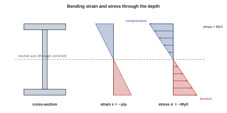
When a beam sags, its top fibres shorten and its bottom fibres lengthen. Somewhere between them is a surface whose length does not change, the neutral surface. Its intersection with a cross-section is the neutral axis. If the beam bends into an arc of radius \(\rho\) (the radius of curvature), a fibre at a distance \(y\) above the neutral surface lies on an arc of radius \(\rho - y\). Comparing arc lengths gives the normal strain:
where \(\kappa = 1/\rho\) is the curvature. The strain varies linearly with distance from the neutral axis, compressive above it and tensile below it for a sagging beam. This follows from geometry alone; it does not depend on the material.
The flexure formula
For a linear elastic material, \(\sigma_x = E\varepsilon_x = -E\,y/\rho\), so the stress is also linear in \(y\). Two equilibrium conditions fix the rest. First, a beam in pure bending carries no net axial force, so the stresses over the section must add to zero:
The integral \(\int y\,dA\) is zero only if \(y\) is measured from the centroid. So the neutral axis passes through the centroid of the cross-section. Second, the moment of the stresses about the neutral axis must equal the internal bending moment:
where \(I\) is the second moment of area (moment of inertia) of the section about the neutral axis. This gives the moment–curvature relation \(1/\rho = M/(EI)\), the basis of deflection calculations in lesson 10. Eliminating \(\rho\) gives the flexure formula:
Here \(c\) is the distance from the neutral axis to the extreme fibre and \(S = I/c\) is the elastic section modulus. The negative sign simply says that positive moment causes compression above the neutral axis. In practice engineers find the magnitude from \(Mc/I\) and decide tension or compression by looking at which face is stretched.
Second moment of area and the parallel axis theorem
For a rectangle of width \(b\) and depth \(h\) about its centroidal axis, \(I = bh^3/12\), and the section modulus is \(S = bh^2/6\). The cube on the depth is why joists are placed on edge: a 38 × 235 mm joist is about 38 times stiffer and 6.2 times stronger in bending on edge than lying flat, for the same amount of wood.
Most sections are built from simple shapes. The second moment of area of a composite shape about its centroidal axis is found with the parallel axis theorem:
where \(I_i\) is each part's own centroidal moment of inertia, \(A_i\) its area and \(d_i\) the distance from its centroid to the centroid of the whole section. The \(A d^2\) terms usually dominate, which is the mathematical reason flanges are so effective: they place a lot of area far from the neutral axis. Rolled steel sections have their properties tabulated, so the theorem is mostly used for built-up girders, precast concrete sections and composite members.
Worked problem
Stress in a timber joist
A floor joist with actual dimensions 38 mm × 235 mm spans 4.0 m simply supported and carries a uniform load of 1.6 kN/m. Find the maximum bending stress.
Show solution
- \[M_{\max} = \frac{wL^2}{8} = \frac{1.6 \times 4.0^2}{8} = 3.2\ \text{kN·m} = 3.2 \times 10^6\ \text{N·mm}\]
- \[S = \frac{b\,h^2}{6} = \frac{38 \times 235^2}{6} = 349\,800\ \text{mm}^3\]
- \[\sigma_{\max} = \frac{M}{S} = \frac{3.2 \times 10^6}{349\,800} = 9.15\ \text{MPa}\]
Answer: About 9.2 MPa, compression at the top and tension at the bottom. This is then compared with the specified bending strength for the species and grade, adjusted for load duration and other factors in the timber design standard.
Worked problem
A T-section with unequal stresses
A T-section has a flange 150 mm wide and 20 mm thick on top of a web 20 mm thick and 180 mm deep (total depth 200 mm). It carries a positive moment of 12 kN·m. Find the neutral axis, \(I\), and the maximum tensile and compressive stresses.
Show solution
- Measure \(y\) up from the bottom. Web: \(A_1 = 3\,600\ \text{mm}^2\), \(\bar y_1 = 90\ \text{mm}\). Flange: \(A_2 = 3\,000\ \text{mm}^2\), \(\bar y_2 = 190\ \text{mm}\).
- \[\bar y = \frac{3600(90) + 3000(190)}{6600} = 135.5\ \text{mm from the bottom}\]
- Web: \(I_1 = 20(180)^3/12 = 9.72 \times 10^6\), \(d_1 = 45.5\), \(A_1d_1^2 = 7.45 \times 10^6\ \text{mm}^4\).
- Flange: \(I_2 = 150(20)^3/12 = 0.10 \times 10^6\), \(d_2 = 54.5\), \(A_2d_2^2 = 8.91 \times 10^6\ \text{mm}^4\).
- Total \(I = 9.72 + 7.45 + 0.10 + 8.91 = 26.18 \times 10^6\ \text{mm}^4\).
- Top fibre: \(c_t = 200 - 135.5 = 64.5\ \text{mm}\); \(\sigma = 12 \times 10^6 \times 64.5/26.18 \times 10^6 = 29.6\ \text{MPa}\) compression.
- Bottom fibre: \(c_b = 135.5\ \text{mm}\); \(\sigma = 12 \times 10^6 \times 135.5/26.18 \times 10^6 = 62.1\ \text{MPa}\) tension.
Answer: The neutral axis sits 135.5 mm above the bottom. The bottom of the web is stressed to 62 MPa in tension, more than twice the top compression, because it is further from the neutral axis.
The T-section example shows that unsymmetrical sections have two section moduli. For a material with different strengths in tension and compression, such as cast iron or concrete, the orientation matters: put the wide flange on the side whose material is weaker, so it is closer to the neutral axis. In a reinforced concrete T-beam, the slab acts as a compression flange at midspan, which is very efficient, while the steel at the bottom takes the tension.
Beyond first yield: the plastic moment
The flexure formula is valid only while the extreme fibre remains elastic. The moment at which the extreme fibre first reaches yield is the yield moment \(M_y = S\,\sigma_y\). A ductile steel beam does not fail there. As the moment increases, yielding spreads inward from the top and bottom until the whole section has yielded, with uniform compression above the neutral axis and uniform tension below. The moment at that state is the plastic moment:
where \(Z\) is the plastic section modulus. For a rectangle, \(Z = bh^2/4\), 1.5 times the elastic modulus; for a typical wide-flange shape the ratio \(Z/S\), called the shape factor, is about 1.1 to 1.2. Steel design codes for compact sections base bending resistance on \(Z\), which is one reason the mechanics of this lesson is the starting point, not the end point, of steel design.
Composite beams and the transformed section
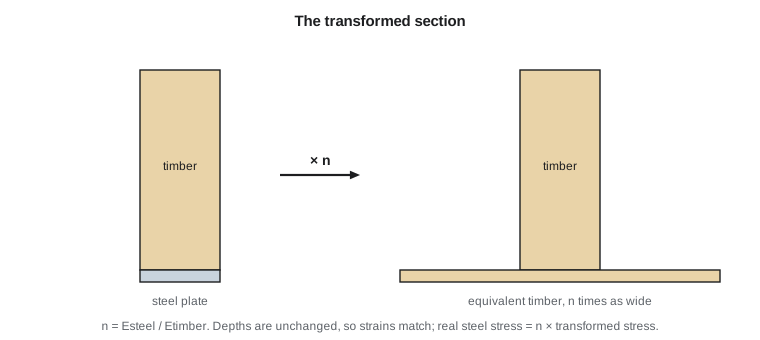
Many beams combine two materials: timber with steel side plates, steel girders with a concrete deck, and reinforced concrete itself. Plane sections still remain plane, so the strain is still linear, but the stress jumps at the interface because the moduli differ. The transformed section method handles this neatly. Choose one material as the reference and define the modular ratio \(n = E_2/E_1\). Replace material 2 with an equivalent amount of material 1 whose width is multiplied by \(n\) (keeping the depth the same). The transformed section is homogeneous, so the flexure formula applies. Stresses in the transformed material are then multiplied by \(n\) to get the real stresses.
Worked problem
A timber beam with a steel plate
A timber beam 100 mm wide and 250 mm deep (\(E_w = 10\ \text{GPa}\)) has a steel plate 100 mm wide and 10 mm thick (\(E_s = 200\ \text{GPa}\)) bonded to its bottom face. The section carries 25 kN·m. Find the maximum stresses in the timber and the steel.
Show solution
- Modular ratio \(n = 200/10 = 20\). The steel transforms to timber 2,000 mm wide and 10 mm thick, area 20,000 mm\(^2\).
- From the bottom: timber \(A = 25\,000\), \(\bar y = 135\); transformed steel \(A = 20\,000\), \(\bar y = 5\). Neutral axis \(\bar y = (25\,000 \times 135 + 20\,000 \times 5)/45\,000 = 77.2\ \text{mm}\).
- Timber: \(I = 100(250)^3/12 + 25\,000(57.8)^2 = 130.2 \times 10^6 + 83.5 \times 10^6\). Steel: \(I = 2000(10)^3/12 + 20\,000(72.2)^2 = 0.17 \times 10^6 + 104.3 \times 10^6\).
- Total transformed \(I = 318.2 \times 10^6\ \text{mm}^4\).
- Top of timber, \(c = 260 - 77.2 = 182.8\ \text{mm}\): \(\sigma_w = 25 \times 10^6 \times 182.8/318.2 \times 10^6 = 14.4\ \text{MPa}\) compression.
- Bottom of steel, \(c = 77.2\ \text{mm}\): transformed stress \(6.07\ \text{MPa}\), real steel stress \(20 \times 6.07 = 121\ \text{MPa}\) tension.
Answer: Timber 14.4 MPa compression at the top, steel 121 MPa tension at the bottom. A thin plate lowers the neutral axis sharply and greatly increases the stiffness.
Section properties by code
Built-up sections are tedious to handle by hand. The program below takes any section made of rectangles, finds its centroid and second moment of area with the parallel axis theorem, and reports the two section moduli. It checks the T-section from the example and then evaluates a welded plate girder.
# Centroid, I and section moduli of a section made of rectangles
# Each rectangle: (width b, height h, y of its bottom edge), all in mm
def properties(name, rects):
    A = sum(b * h for b, h, y0 in rects)
    ybar = sum(b * h * (y0 + h / 2) for b, h, y0 in rects) / A
    I = sum(b * h**3 / 12 + b * h * (y0 + h / 2 - ybar) ** 2 for b, h, y0 in rects)
    top = max(y0 + h for b, h, y0 in rects)
    S_top, S_bot = I / (top - ybar), I / ybar
    print(f"{name}: A = {A:,.0f} mm2, ybar = {ybar:.1f} mm, I = {I/1e6:.2f} x10^6 mm4, "
          f"S_top = {S_top/1e3:.1f} x10^3 mm3, S_bot = {S_bot/1e3:.1f} x10^3 mm3")
    return I, ybar

properties("T-section", [(20, 180, 0), (150, 20, 180)])
# Welded girder: 300 x 25 flanges, 1000 x 12 web
I, yb = properties("Plate girder", [(300, 25, 0), (12, 1000, 25), (300, 25, 1025)])
M = 1500e6                                   # 1500 kN*m in N*mm
print(f"Girder stress under 1500 kN*m: {M * (1050 - yb) / I:.0f} MPa at the extreme fibre")T-section: A = 6,600 mm2, ybar = 135.5 mm, I = 26.18 x10^6 mm4, S_top = 405.7 x10^3 mm3, S_bot = 193.3 x10^3 mm3 Plate girder: A = 27,000 mm2, ybar = 525.0 mm, I = 4940.62 x10^6 mm4, S_top = 9410.7 x10^3 mm3, S_bot = 9410.7 x10^3 mm3 Girder stress under 1500 kN*m: 159 MPa at the extreme fibre
The plate girder's flanges hold only about 55 % of the steel, yet they supply about 80 % of its second moment of area. That is the case for the I-shape in one number.
Common mistakes
MistakeMeasuring \(y\) from the bottom of the section instead of from the neutral axis in \(\sigma = My/I\).
InsteadFind the centroid first; \(y\) and \(c\) are measured from it.
MistakeForgetting the \(A d^2\) terms when combining shapes.
InsteadEach part needs \(I_i + A_i d_i^2\) about the overall centroidal axis.
MistakeAssuming the extreme tensile and compressive stresses are equal for any section.
InsteadThey are equal only for sections symmetric about the neutral axis; otherwise use the two different values of \(c\).
MistakeUsing the transformed-section stress directly for the transformed material.
InsteadMultiply by the modular ratio \(n\) to get the real stress in that material.
Summary and key terms
- Plane sections remain plane, so bending strain varies linearly with distance from the neutral axis.
- For a linear elastic beam, the neutral axis passes through the centroid.
- The flexure formula is \(\sigma = My/I\); the maximum stress is \(Mc/I = M/S\).
- Moment and curvature are related by \(1/\rho = M/(EI)\).
- Use the parallel axis theorem \(I = \sum(I_i + A_id_i^2)\) for built-up sections.
- Ductile beams reach the plastic moment \(M_p = Z\sigma_y\), above the yield moment \(S\sigma_y\).
- Composite beams are analyzed with a transformed section using the modular ratio \(n = E_2/E_1\).
- Neutral axis
- The line in a cross-section where the bending stress and strain are zero.
- Curvature
- The reciprocal of the radius of curvature of the bent beam axis.
- Second moment of area
- The integral of the squared distance from an axis over the area; a measure of bending stiffness.
- Section modulus
- I divided by the distance to the extreme fibre; maximum stress equals M divided by S.
- Parallel axis theorem
- I about any axis equals I about a parallel centroidal axis plus A times the squared distance between them.
- Plastic moment
- The moment at which the whole cross-section has yielded.
- Shape factor
- The ratio of plastic to elastic section modulus.
- Modular ratio
- The ratio of the moduli of two materials in a composite section.
Practice problems
Work each problem on paper first, then reveal the answer to check.
A 50 × 200 mm rectangular beam carries 6 kN·m. Find \(\sigma_{\max}\).
Show answer
\(S = 50 \times 200^2/6 = 333\,300\ \text{mm}^3\), \(\sigma = 18.0\ \text{MPa}\).
By what factor does the bending strength of a rectangle increase if its depth doubles?
Show answer
By 4, since \(S \propto h^2\).
Find the plastic modulus of a 100 × 300 mm rectangle and its plastic moment for \(\sigma_y = 250\ \text{MPa}\).
Show answer
\(Z = bh^2/4 = 2.25 \times 10^6\ \text{mm}^3\), \(M_p = 562.5\ \text{kN·m}\).
A beam has \(EI = 20 \times 10^{12}\ \text{N·mm}^2\) and carries 50 kN·m. Find its radius of curvature.
Show answer
\(\rho = EI/M = 20 \times 10^{12}/50 \times 10^6 = 400\,000\ \text{mm} = 400\ \text{m}\).
In the transformed section of a concrete slab on a steel girder with \(n = 8\), how is the slab transformed if steel is the reference material?
Show answer
Its width is divided by 8, because concrete is less stiff than steel.
Why should a cast iron T-beam under positive moment have its flange at the bottom?
Show answer
Cast iron is weaker in tension; the flange side is closer to the neutral axis, so the tensile stress there is smaller.
Lesson quiz · 5 questions
Score 60% or more to complete this lesson.
Create a free account to save your progress, take quizzes and earn a certificate.