
PET-240 · Lesson 1 of 12 · 26 min
Stress, strain and material behaviour
Statics, which you met in ENGG-130, treats every body as rigid. It tells you the forces in a truss member, the reactions under a beam and the tension in a cable, but it cannot tell you whether the member will break, stretch too far or buckle. Mechanics of solids (also called mechanics of materials or strength of materials) takes the internal forces that statics produces and asks what they do to a real, deformable material. The two central quantities are stress, which measures how intensely the internal force is spread over the material, and strain, which measures how much the material deforms.
Every later lesson in this course builds on the ideas introduced here. Axial members, shafts, beams, pressure vessels and columns are all analyzed by the same three steps: use equilibrium to find the internal force or moment, use geometry to describe how the member deforms, and use the material law to connect the two. Keep that pattern in mind and the formulas stop looking like a list to memorize.
Internal forces and the method of sections
To find the stress inside a member, you first need the internal force acting on a cut through it. The method of sections does this: pass an imaginary plane through the member, draw a free-body diagram of one side, and apply equilibrium. In general the cut exposes six internal actions. The normal force \(N\) acts perpendicular to the cut and stretches or squeezes the member. Two shear forces \(V_y\) and \(V_z\) act in the plane of the cut and try to slide one side past the other. The torque \(T\) twists the member about its axis, and two bending moments \(M_y\) and \(M_z\) bend it.
Most members carry only one or two of these at a time, and this course takes them one by one: normal force in lessons 1 and 2, torque in lesson 3, bending moment and shear in lessons 4 to 6, and combinations in lesson 7. Whatever the member, always find the internal action before you try to find a stress.
Normal stress
Stress is force per unit area. When the internal force is perpendicular to the cut, it produces normal stress, written \(\sigma\) (sigma). If a prismatic bar carries an axial load \(P\) through the centroid of its cross-section, and you look far enough from the points where the load is applied, the stress is spread uniformly over the area \(A\):
In SI units, force in newtons divided by area in square metres gives pascals (Pa). Engineering stresses are large, so they are almost always reported in megapascals: \(1\ \text{MPa} = 10^6\ \text{Pa} = 1\ \text{N/mm}^2\). That last equivalence is handy, because if you keep forces in newtons and dimensions in millimetres, the stress comes out in MPa directly. In US customary units, stress is reported in pounds per square inch (psi) or kips per square inch (ksi), where 1 kip is 1,000 lb. For reference, \(1\ \text{ksi} \approx 6.895\ \text{MPa}\).
The sign convention is simple: tensile stress, which pulls on the cut surface, is positive; compressive stress, which pushes, is negative. Some design codes and textbooks quote compressive stresses as positive numbers with a label, so always check which convention a source uses.
The uniform stress assumption depends on Saint-Venant's principle. Close to a concentrated load, a bolt hole or a sudden change in section, the stress is far from uniform. But a short distance away, roughly one member width, the local disturbance dies out and the stress settles to \(P/A\). The concentrated peaks near holes and fillets are handled with stress concentration factors, which lesson 2 introduces.
Average shear stress and bearing stress
When the internal force lies in the plane of the cut, it produces shear stress, written \(\tau\) (tau). Shear stress is rarely uniform, but in connections such as bolts, pins and rivets, design is based on the average value over the shear area:
The key step is counting the shear planes. A bolt joining two plates in a lap joint is in single shear: one plane carries the whole load, so \(V = P\). A clevis pin passing through a fork and a central lug is in double shear: two planes each carry half the load, so \(V = P/2\) on each plane. Drawing the free-body diagram of the pin, with the cut planes shown, is the reliable way to get this right.
Connections can also fail by bearing, where the bolt crushes the edge of the hole or the hole edge crushes the bolt. The average bearing stress is the load divided by the projected contact area, which for a bolt of diameter \(d\) bearing on a plate of thickness \(t\) is \(d \times t\):
Worked problem
Stress in a hanger rod and its pin
A steel rod of diameter 20 mm hangs a load of 45 kN. At its upper end, a clevis with a 16 mm pin in double shear connects the rod to a bracket. The bracket plate is 12 mm thick. Find the normal stress in the rod, the average shear stress in the pin and the bearing stress between the pin and the bracket plate.
Show solution
- Rod area: \(A = \pi d^2/4 = \pi (20)^2/4 = 314.2\ \text{mm}^2\).
- \[\sigma = \frac{P}{A} = \frac{45\,000}{314.2} = 143.2\ \text{MPa (tension)}\]
- Pin area: \(A_p = \pi (16)^2/4 = 201.1\ \text{mm}^2\). In double shear, each plane carries \(V = 45/2 = 22.5\ \text{kN}\).
- \[\tau_{\text{avg}} = \frac{22\,500}{201.1} = 111.9\ \text{MPa}\]
- The bracket plate (the central lug) carries the full 45 kN through a projected area \(d\,t = 16 \times 12 = 192\ \text{mm}^2\).
- \[\sigma_b = \frac{45\,000}{192} = 234.4\ \text{MPa}\]
Answer: Rod 143 MPa in tension, pin 112 MPa in shear, bearing 234 MPa. Each value is then compared with the strength of the relevant material and failure mode.
Normal and shear strain
Strain describes deformation in a way that does not depend on the size of the member. Normal strain \(\varepsilon\) (epsilon) is the change in length per unit original length:
where \(\delta\) is the elongation and \(L_0\) the original length. Strain is dimensionless, but it is often written as mm/mm, in./in., or in microstrain (\(\mu\varepsilon\), millionths). A strain of 0.001 is 1,000 microstrain, or 0.1 %. Extension is positive, shortening negative.
Shear strain \(\gamma\) (gamma) is the change in angle, in radians, between two lines that were originally perpendicular. If a small square element distorts into a rhombus whose corner angle shrinks from \(\pi/2\) to \(\pi/2 - \gamma\), the shear strain is \(\gamma\). Shear strains appear wherever there is shear stress: in a twisted shaft, in the web of a beam, and in rubber bearing pads under bridge girders.
The stress–strain diagram
The link between stress and strain is a property of the material and must be measured. The standard measurement is the tension test: a carefully machined specimen is pulled in a testing machine while the load and the elongation over a gauge length are recorded. Dividing the load by the original area gives engineering stress, and dividing the elongation by the original gauge length gives engineering strain. Plotting one against the other gives the stress–strain diagram.
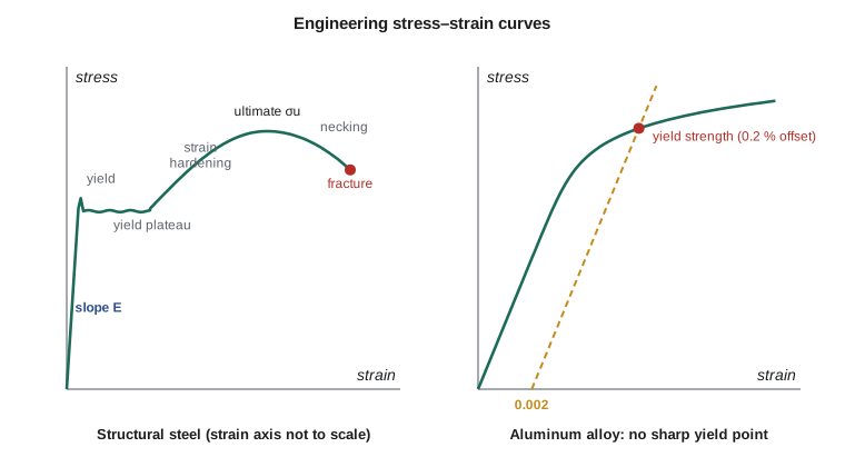
For a ductile structural steel the curve has several distinct regions.
- Linear elastic region. Stress is proportional to strain up to the proportional limit. If the load is removed, the specimen returns to its original length.
- Yielding. At the yield stress \(\sigma_y\) the material begins to deform plastically. Mild steels show a flat yield plateau where strain grows with almost no increase in stress, often to 10 or 15 times the yield strain.
- Strain hardening. After the plateau, the material stiffens again as its crystal structure rearranges, and stress rises to the ultimate stress \(\sigma_u\), the highest point on the engineering curve.
- Necking and fracture. Beyond the ultimate stress the deformation concentrates in a narrow neck. The load the specimen can carry drops, so engineering stress falls until the specimen fractures.
Many materials, such as aluminum alloys, high-strength steels and cold-worked metals, have no sharp yield point. For these, the yield strength is defined by the offset method: draw a line parallel to the initial elastic slope starting at a strain of 0.002 (0.2 %), and take the stress where it meets the curve.
Ductility, the ability to deform plastically before fracture, is reported as percent elongation at fracture or percent reduction in area. Ductile materials such as structural steel give visible warning before failure and redistribute load in redundant structures. Brittle materials such as cast iron, glass and plain concrete fracture with little plastic strain, and concrete in particular is far stronger in compression than in tension. Designers treat the two classes differently: ductile members are usually designed against yielding, brittle ones against fracture with larger safety margins.
Hooke's law, Poisson's ratio and the shear modulus
In the linear elastic region, stress is proportional to strain. The constant of proportionality is the modulus of elasticity, or Young's modulus, \(E\):
\(E\) measures stiffness, not strength. All structural steels, from mild steel to high-strength grades, have nearly the same modulus, about 200 GPa (29,000 ksi), even though their yield strengths differ by a factor of two or more. A stronger steel will carry more load before yielding, but it will not deflect less under the same load. This is why stiffness, not strength, often governs the design of long beams and slender columns.
When a bar stretches axially, it also contracts laterally. Poisson's ratio \(\nu\) (nu) is the ratio of the lateral strain to the axial strain, with a sign that makes it positive:
For most metals \(\nu\) is between 0.25 and 0.35; steel is usually taken as 0.30 and aluminum as 0.33. Rubber is close to 0.5, the theoretical upper limit for an isotropic material, which corresponds to no change in volume.
Shear behaves in a similar way. In the linear range, shear stress is proportional to shear strain, \(\tau = G\gamma\), where \(G\) is the shear modulus (modulus of rigidity). For an isotropic material the three elastic constants are not independent:
For steel, \(G = 200/(2 \times 1.3) \approx 77\ \text{GPa}\) (about 11,200 ksi).
| Material | E (GPa) | G (GPa) | Poisson ratio | Yield strength (MPa) |
|---|---|---|---|---|
| Structural steel | 200 | 77 | 0.30 | 250–450 |
| Aluminum 6061-T6 | 69 | 26 | 0.33 | about 275 |
| Concrete (normal density) | 25–35 | — | 0.15–0.20 | compressive strength 25–50 |
| Douglas fir (along grain) | about 12 | — | — | varies with grade |
| Copper | about 117 | about 44 | 0.34 | 70 (annealed) to 300+ |
Worked problem
Elongation and diameter change of a test specimen
A 12.5 mm diameter aluminum specimen with a 50 mm gauge length carries a tensile load of 18 kN. Using \(E = 69\ \text{GPa}\) and \(\nu = 0.33\), find the stress, the elongation of the gauge length and the change in diameter. Assume the stress is below the proportional limit.
Show solution
- Area \(A = \pi (12.5)^2/4 = 122.7\ \text{mm}^2\).
- \[\sigma = \frac{18\,000}{122.7} = 146.7\ \text{MPa}\]
- \[\varepsilon = \frac{\sigma}{E} = \frac{146.7}{69\,000} = 2.126 \times 10^{-3}\]
- Elongation: \(\delta = \varepsilon L_0 = 0.002126 \times 50 = 0.106\ \text{mm}\).
- Lateral strain: \(\varepsilon_{\text{lat}} = -\nu\varepsilon = -0.33 \times 0.002126 = -7.02 \times 10^{-4}\).
- Change in diameter: \(\Delta d = \varepsilon_{\text{lat}}\,d = -7.02 \times 10^{-4} \times 12.5 = -0.0088\ \text{mm}\).
Answer: The stress is 147 MPa, the gauge length stretches by 0.106 mm and the diameter shrinks by about 0.009 mm. Lateral changes are small, which is why they need precise instruments to measure.
Reading test data with code
Laboratories record hundreds of load–elongation points, and the modulus and offset yield strength are found by processing that data. The short program below generates a realistic set of points for an aluminum alloy, fits the elastic slope to the early points by least squares, and then finds where the 0.2 % offset line crosses the curve.
# Find E and the 0.2% offset yield strength from tension-test data
import math

E_true, sy_true, n = 69000.0, 275.0, 12.0   # MPa; Ramberg-Osgood style curve
def strain(stress):
    return stress / E_true + 0.002 * (stress / sy_true) ** n

stresses = [5.0 * i for i in range(1, 63)]          # 5 to 310 MPa
data = [(strain(s), s) for s in stresses]

# Least-squares slope through the origin using points below 120 MPa
pts = [(e, s) for e, s in data if s <= 120]
E_fit = sum(e * s for e, s in pts) / sum(e * e for e, s in pts)

# Offset line: s = E_fit * (e - 0.002). Find the first point where the curve falls below it
for (e1, s1), (e2, s2) in zip(data, data[1:]):
    g1 = s1 - E_fit * (e1 - 0.002)
    g2 = s2 - E_fit * (e2 - 0.002)
    if g1 > 0 >= g2:
        t = g1 / (g1 - g2)                 # linear interpolation between points
        sy = s1 + t * (s2 - s1)
        break

print(f"Fitted modulus E   = {E_fit / 1000:.1f} GPa")
print(f"0.2% offset yield  = {sy:.0f} MPa")
print(f"Strain at 310 MPa = {strain(310):.4f}")Fitted modulus E = 69.0 GPa 0.2% offset yield = 275 MPa Strain at 310 MPa = 0.0129
Real data are noisier than this, so laboratories usually fit the elastic slope over a stated stress range and use extensometers rather than crosshead movement to measure strain. The idea, though, is exactly what the code does.
Allowable stress, factors of safety and limit states
A member must carry its loads with a margin against failure. The classical way to express that margin is the factor of safety: the ratio of the failure load (or stress) to the allowable load (or stress). If a steel with a yield strength of 350 MPa is designed with a factor of safety of 1.67 against yielding, the allowable stress is \(350/1.67 = 210\ \text{MPa}\). This approach is called allowable stress design or working stress design.
Modern structural codes use limit states design, which separates the uncertainty in the loads from the uncertainty in the resistance. Loads are multiplied by load factors greater than one, so a dead load might be factored by 1.25 and a live load by 1.5. The nominal resistance is multiplied by a resistance factor \(\phi\) less than one. The member is adequate when the factored resistance is at least the factored load effect.
In Canada, steel buildings are designed to CSA S16, Design of steel structures, with loads from the National Building Code of Canada, and highway bridges to CSA S6. A common structural steel grade is CSA G40.21 350W, with a minimum yield strength of 350 MPa. This course gives you the mechanics behind those codes; the code provisions themselves are covered in steel and concrete design courses.
Whichever philosophy a code uses, the mechanics are the same: you still need to know the stress or internal force a load produces. That is the job of this course.
Common mistakes
MistakeUsing the total load as the shear on each plane of a pin in double shear.
InsteadDraw the pin's free-body diagram. With two shear planes, each carries half the load.
MistakeMixing millimetres and metres in \(\sigma = P/A\).
InsteadKeep newtons and millimetres together to get MPa, or newtons and square metres to get Pa, and never mix the two.
MistakeAssuming a stronger steel is also a stiffer steel.
InsteadStrength depends on the grade; stiffness (\(E\)) is almost the same for all steels. A higher-strength beam deflects just as much under the same load.
MistakeApplying Hooke's law beyond the proportional limit.
Instead\(\sigma = E\varepsilon\) holds only in the linear elastic range. Beyond yield, use the measured stress–strain curve.
Summary and key terms
- Find the internal force with the method of sections before computing any stress.
- Normal stress \(\sigma = P/A\) acts perpendicular to a cut; average shear stress \(\tau = V/A\) acts in its plane.
- Count shear planes carefully: single shear carries \(P\), double shear \(P/2\) per plane.
- Strain is deformation per unit length (normal) or change in a right angle (shear), and is dimensionless.
- The stress–strain diagram gives the modulus, yield strength, ultimate strength and ductility.
- In the elastic range \(\sigma = E\varepsilon\), \(\tau = G\gamma\) and \(G = E/[2(1+\nu)]\).
- Codes provide margins through factors of safety or through load and resistance factors.
- Normal stress
- Internal force per unit area acting perpendicular to a surface.
- Shear stress
- Internal force per unit area acting in the plane of a surface.
- Bearing stress
- Contact pressure between a fastener and the edge of a hole, based on the projected area.
- Normal strain
- Change in length divided by original length.
- Shear strain
- Change, in radians, of an originally right angle.
- Modulus of elasticity
- The slope of the linear part of the stress–strain curve; a measure of stiffness.
- Yield strength
- The stress at which permanent deformation begins, often defined by the 0.2 % offset.
- Ultimate stress
- The highest engineering stress a material reaches in a tension test.
- Poisson's ratio
- The negative ratio of lateral strain to axial strain.
- Factor of safety
- The ratio of failure capacity to the load or stress allowed in service.
Practice problems
Work each problem on paper first, then reveal the answer to check.
A 25 mm diameter bar carries 60 kN in tension. What is the normal stress?
Show answer
\(A = 490.9\ \text{mm}^2\), so \(\sigma = 60\,000/490.9 = 122\ \text{MPa}\).
A 20 mm bolt in single shear carries 40 kN. What is the average shear stress?
Show answer
\(A = 314.2\ \text{mm}^2\), \(\tau = 40\,000/314.2 = 127\ \text{MPa}\).
A 2.0 m steel bar (\(E = 200\ \text{GPa}\)) is stressed to 150 MPa. How much does it stretch?
Show answer
\(\varepsilon = 150/200\,000 = 0.00075\), so \(\delta = 0.00075 \times 2000 = 1.5\ \text{mm}\).
A material has \(E = 105\ \text{GPa}\) and \(\nu = 0.34\). Estimate \(G\).
Show answer
\(G = 105/(2 \times 1.34) = 39.2\ \text{GPa}\).
A steel with \(\sigma_y = 350\ \text{MPa}\) is designed with a factor of safety of 2.0 against yield. What is the allowable stress?
Show answer
\(350/2.0 = 175\ \text{MPa}\).
Why is the yield plateau of mild steel useful to a structural engineer?
Show answer
It gives large visible deformation before fracture and lets indeterminate structures redistribute load after the most stressed parts yield.
Lesson quiz · 5 questions
Score 60% or more to complete this lesson.
Create a free account to save your progress, take quizzes and earn a certificate.