
MEC-260 · Lesson 6 of 12 · 24 min
Auxiliary views and true size
The redesigned BB-210 has one feature that the old bracket lacked: a small flat pad machined on the upper front of the upright, tilted 30° from horizontal toward the front of the pump, with a tapped hole for a grease fitting. The tilt lets a technician reach the fitting with a grease gun without removing the coupling guard. On the three principal views the pad is a nuisance. In the side view it appears as a sloping line; in the front and top views it appears as a squashed rectangle, and the tapped hole appears as an ellipse. None of these views shows the pad's real size or the hole's true position. Owen's job in this lesson is to add an auxiliary view that looks straight at the pad.
When principal views are not enough
Principal views show surfaces true size only when the surfaces are parallel to the principal planes. Lesson 3 showed that an inclined surface, perpendicular to one principal plane and tilted to the others, appears as an edge in one view and foreshortened in the other two. Features on that surface, such as holes, slots and outlines, are distorted too: circles become ellipses, and lengths shrink by the cosine of the tilt angle. Dimensioning a distorted feature is unreliable and confusing.
An auxiliary view solves the problem by projecting onto a plane parallel to the inclined surface. In that view the surface appears true size and shape, its features appear undistorted, and they can be dimensioned directly. Auxiliary views are also the basis of descriptive geometry, the graphical method of finding true lengths, true angles, intersections and clearances in three dimensions, which engineers used for centuries before computers and which still underlies how modelling programs compute such things.
Primary auxiliary views
A primary auxiliary view is projected from one of the principal views, the one in which the inclined surface appears as an edge. Imagine adding a new face to the glass box, parallel to the inclined surface, hinged to the face on which the surface appears as an edge. The hinge line is called the fold line or reference line. Unfolding the new face gives a view whose line of sight is perpendicular to the inclined surface.
The construction follows directly. In the view showing the surface as an edge, draw projection lines perpendicular to that edge. Draw a fold line parallel to the edge, a convenient distance away. Then transfer distances: each point in the auxiliary view lies along its projection line at the same distance from the auxiliary fold line as the point lies from the fold line in a related view, the view adjacent to the one you projected from. This distance transfer is the key idea, and it is the same as the depth transfer between top and side views in ordinary orthographic projection.
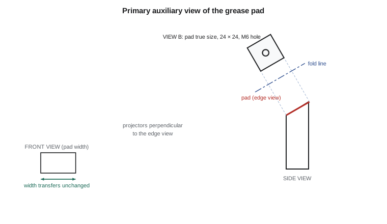
Auxiliary views are classified by the principal view they are projected from. A depth auxiliary view is projected from the front view and shows depth true; a height auxiliary view is projected from the top view and shows height true; a width auxiliary view is projected from a side view and shows width true. The names describe which principal dimension transfers unchanged into the auxiliary view.
Partial auxiliary views
A full auxiliary view would show the whole part, but everything except the inclined surface would then be foreshortened and confusing. Standard practice is to draw a partial auxiliary view, showing only the inclined surface and its features, ended with a break line or simply left open. In the same spirit, the foreshortened portion of the inclined surface in the principal views can often be omitted or shown in outline, with the true details left to the auxiliary view. The BB-210 drawing shows the pad as a partial auxiliary view labelled VIEW B, with a viewing arrow on the side view.
When the auxiliary view cannot be placed in its projected position because of space, it may be moved, provided it keeps its orientation and is labelled with a viewing arrow and letter. Rotating an auxiliary view to fit the sheet is allowed by ASME Y14.3 if the rotation angle and direction are stated, but it makes the view harder to relate to the parent and should be a last resort.
Worked problem
True shape of the grease pad
In the top view, the grease pad appears as a rectangle 24.0 mm wide and 20.8 mm deep. The pad is tilted 30° from horizontal about an axis parallel to the width. What is its true shape?
Show solution
- The width is parallel to the tilt axis, so it is not foreshortened: 24.0 mm.
- The depth seen in the top view is the true depth times \(\cos 30^\circ\), because the pad slopes in that direction.
- \[d_{\text{true}} = \frac{20.8}{\cos 30^\circ} = \frac{20.8}{0.866} = 24.0\ \text{mm}\]
- In the front view the pad's height extent is \(24.0 \sin 30^\circ = 12.0\) mm, also foreshortened.
Answer: The pad is a 24 mm square. Neither principal view shows it as a square, which is exactly why an auxiliary view is needed to dimension it and the centred hole.
True length of a line
Descriptive geometry starts with lines. A line appears true length in any view projected onto a plane parallel to it. A line parallel to a principal plane, called a principal line, appears true length in that principal view: a horizontal line is true length in the top view, a frontal line in the front view, a profile line in the side view. A line that is not parallel to any principal plane, an oblique line, appears foreshortened in all three principal views, and its true length must be found with an auxiliary view projected perpendicular to one of its views.
The angle a line makes with a principal plane appears true only in a view in which the line is true length and the plane appears as an edge. For example, the slope of a pipe, its angle with the horizontal plane, appears true in an auxiliary view projected from the top view perpendicular to the pipe, because that view shows the pipe true length and the horizontal plane as an edge. Pipe designers, structural detailers and mining engineers used these constructions daily, and the same logic appears whenever you set up a section plane or view direction in a model.
Point view of a line, edge view of a plane, dihedral angles
Further auxiliary views solve harder problems. Projecting along a true-length line gives its point view, in which the whole line appears as a single point. Any plane containing that line then appears as an edge. This gives a general method for finding the edge view of any plane: find a true-length line in the plane, then project along it. Once a plane is seen as an edge, a further auxiliary view projected perpendicular to that edge shows the plane in true shape. Since an oblique surface requires two steps, this is called a secondary auxiliary view.
The dihedral angle between two planes, the angle between two surfaces of a part, appears true in the view where their line of intersection appears as a point, because both planes then appear as edges. On the BB-210 the pad meets the front face of the upright along a horizontal line, which already appears as a point in the side view, so the side view shows the 120° angle between the two surfaces through the material directly. On a bracket with a compound angle, two auxiliary steps would be needed.
The program does these calculations with vectors, which is how a modelling program does them. It finds the true length of a line and its angles with the three principal planes, the true shape of the pad, and the dihedral angle between the pad and the front of the upright from their normal vectors.
import math

def sub(a, b): return tuple(x - y for x, y in zip(a, b))
def dot(a, b): return sum(x * y for x, y in zip(a, b))
def cross(a, b): return (a[1]*b[2] - a[2]*b[1], a[2]*b[0] - a[0]*b[2], a[0]*b[1] - a[1]*b[0])
def norm(a): return math.sqrt(dot(a, a))

# A line from P to Q, coordinates in mm (x right, y back, z up)
P, Q = (10, 5, 0), (70, 45, 50)
d = sub(Q, P)
print(f"Line PQ: true length = {norm(d):.2f} mm")
for name, plane_normal, view in (("horizontal (top view)", (0, 0, 1), (0, 1)),
                                 ("frontal (front view)", (0, 1, 0), (0, 2)),
                                 ("profile (side view)", (1, 0, 0), (1, 2))):
    projected = math.hypot(d[view[0]], d[view[1]])
    angle = math.degrees(math.asin(abs(dot(d, plane_normal)) / norm(d)))
    print(f"  in the {name:22s}: projected length {projected:6.2f} mm, line makes {angle:5.1f} deg with this plane")

# The inclined grease pad: a flat face whose normal is tilted 30 deg from vertical
# toward the front of the bracket. Its outline in plan (top view) is 24 x 20.8 mm.
tilt = math.radians(30)
n_pad = (0, -math.sin(tilt), math.cos(tilt))
plan_w, plan_d = 24.0, 20.8
true_d = plan_d / math.cos(tilt)
print(f"\nGrease pad: plan view {plan_w} x {plan_d} mm, true shape {plan_w} x {true_d:.1f} mm "
      f"(seen only in an auxiliary view)")

# Dihedral angle between the pad and the vertical front face of the upright (outward normal -y)
n_front = (0, -1, 0)
theta = math.degrees(math.acos(dot(n_pad, n_front)))
print(f"Angle between the outward normals of the pad and the front face: {theta:.1f} deg")
print(f"Dihedral angle measured through the material: {180 - theta:.1f} deg")

# Direction of sight for the primary auxiliary view: along the pad normal.
fold_angle = math.degrees(math.atan2(-n_pad[1], n_pad[2]))
print(f"Auxiliary view is projected from the side view at {fold_angle:.0f} deg from vertical,"
f" with the fold line parallel to the pad's edge view")Line PQ: true length = 87.75 mm in the horizontal (top view) : projected length 72.11 mm, line makes 34.7 deg with this plane in the frontal (front view) : projected length 78.10 mm, line makes 27.1 deg with this plane in the profile (side view) : projected length 64.03 mm, line makes 43.1 deg with this plane Grease pad: plan view 24.0 x 20.8 mm, true shape 24.0 x 24.0 mm (seen only in an auxiliary view) Angle between the outward normals of the pad and the front face: 60.0 deg Dihedral angle measured through the material: 120.0 deg Auxiliary view is projected from the side view at 30 deg from vertical, with the fold line parallel to the pad's edge view
Secondary auxiliary views and oblique surfaces
An oblique surface, tilted to all three principal planes, needs a secondary auxiliary view. First draw a primary auxiliary view in which the surface appears as an edge, by looking along a true-length line that lies in the surface. Then draw a secondary auxiliary view perpendicular to that edge view. The secondary view shows the surface in true shape. Each step adds a fold line, and distances are always transferred from the view two steps back. The process is mechanical once you understand it, and it never depends on the complexity of the object, only on the orientation of the surface.
In practice, oblique surfaces on machined parts are uncommon, because they are expensive to machine and hard to inspect. Designers prefer surfaces with a single tilt, which can be produced by tilting a part once in a vise or fixture. When Farah reviewed an early concept in which the grease pad was tilted in two directions to aim the fitting between two guard bolts, she sent it back: a single 30° tilt, she said, would save a second setup on every one of several hundred brackets a year. Geometry that is easy to draw in a model is not always easy to make.
Auxiliary views and features on inclined surfaces
Holes, slots and bosses on an inclined surface should be dimensioned in the auxiliary view, where they appear true size and their positions can be measured from the edges of the surface. In the principal views, those features appear as ellipses and distorted shapes; showing them in full adds drawing time and clutter without adding information. ASME practice allows such foreshortened features to be omitted from principal views when the auxiliary view defines them, and many drawings show only their centre lines in the principal views to link the views together.
The direction of a hole drilled into an inclined surface matters too. A hole perpendicular to the pad appears as a true circle in the auxiliary view, with its axis appearing true length in the view showing the pad as an edge. The grease hole on the BB-210 is perpendicular to the pad, so it is dimensioned as an M6 tapped hole in VIEW B, with its depth measured along the hole axis, and its axis shown in the side view at 30° from vertical.
Common mistakes
MistakeDimensioning a hole on an inclined face in a principal view where it appears as an ellipse.
InsteadDimension it in an auxiliary view where the face and hole appear true size.
MistakeDrawing the fold line in an arbitrary direction.
InsteadDraw the fold line parallel to the edge view of the inclined surface.
MistakeTransferring distances from the wrong view.
InsteadTransfer distances from the view adjacent to the parent view, two steps back from the new view.
MistakeDrawing a full auxiliary view with every feature foreshortened.
InsteadUse a partial auxiliary view showing only the inclined surface and its features.
MistakeDesigning compound angles without considering manufacture.
InsteadPrefer single-tilt surfaces; each additional angle can add a setup.
Summary and key terms
- Auxiliary views project onto a plane parallel to an inclined surface, showing it in true size and shape.
- A primary auxiliary view is projected from the view in which the surface appears as an edge, with the fold line parallel to that edge.
- Distances from the fold line are transferred from the view adjacent to the parent view.
- Partial auxiliary views show only the inclined surface and its features.
- A line appears true length in a view parallel to it; its angle with a plane is true when the line is true length and the plane is an edge.
- Point views of lines give edge views of planes and true dihedral angles; oblique surfaces need secondary auxiliary views.
- Single-tilt features are easier to machine and inspect than compound angles.
- Auxiliary view
- A view projected onto a plane that is not one of the principal planes, usually parallel to an inclined surface.
- Fold line
- The hinge line between two adjacent views, used as a reference for transferring distances.
- Partial auxiliary view
- An auxiliary view that shows only the inclined feature and omits the rest of the part.
- True length
- The actual length of a line, seen only in a view parallel to it.
- Point view
- A view looking along a line, in which the line appears as a point.
- Edge view
- A view in which a plane appears as a line.
- Dihedral angle
- The angle between two planes, seen true when their intersection appears as a point.
- Secondary auxiliary view
- A view projected from a primary auxiliary view, used to show an oblique surface in true shape.
Practice problems
Work each problem on paper first, then reveal the answer to check.
A surface tilted 40° appears 30 mm deep in the top view. What is its true depth?
Show answer
30 / cos 40° = 39.2 mm.
In which principal view does a horizontal line appear true length?
Show answer
The top view.
What view of a line makes a plane containing that line appear as an edge?
Show answer
The point view of the line.
Why are partial auxiliary views preferred?
Show answer
They show the true-size feature without the foreshortened, confusing remainder of the part.
A line runs from (0, 0, 0) to (30, 40, 0) mm. What is its true length and in which view is it true?
Show answer
50 mm; it is horizontal, so it is true length in the top view.
Change the pad tilt in the program to 45°. What plan depth corresponds to a 24 mm square pad?
Show answer
24 cos 45° = 17.0 mm.
Lesson quiz · 5 questions
Score 60% or more to complete this lesson.
Create a free account to save your progress, take quizzes and earn a certificate.