
MEC-260 · Lesson 3 of 12 · 25 min
Orthographic projection: first and third angle
Tidewater's newest customer is a pump packager in Germany, and the first drawing they sent back to Moncton was marked up in red: the customer had read Tidewater's side view as the opposite side of the bracket and asked why the grease fitting had moved. Nothing had moved. The two companies were using different projection systems. Tidewater, like most North American manufacturers, draws in third-angle projection; the customer, like most of Europe and much of Asia, draws in first-angle projection. Both systems are correct and both are standardized, but they place the views in opposite positions. A small symbol in the title block says which one a drawing uses, and Owen learned in his first month that it is the most important symbol on the sheet.
Projection: from a solid to flat views
A projection maps a three-dimensional object onto a flat plane. Imagine lines of sight, called projectors, passing from every point on the object to the plane. In perspective projection the projectors converge at the viewer's eye, which gives a natural-looking picture but distorts sizes. In parallel projection the projectors are all parallel. When they are also perpendicular to the plane, the projection is orthographic, from the Greek for right-angled drawing. Orthographic views show features that are parallel to the projection plane in their true size and shape, which is exactly what a manufacturer needs.
A single orthographic view shows only two dimensions. The front view of the bracket shows its width and height but says nothing about its depth. To define a part completely we need at least two views, usually three, arranged in a fixed relationship so that each view shares a dimension with its neighbours. The fixed arrangement is what lets a reader find the same feature in every view.
The glass box
The standard way to explain the arrangement is the glass box. Imagine the bracket suspended inside a transparent box with six faces. Project the bracket onto each face, as if tracing its outline on the glass. Then unfold the box onto a flat sheet, hinging the faces about the edges they share with the front face. The six resulting views are the principal views: front, top, right side, left side, bottom and rear. In third-angle projection the box is between the viewer and the object, so each view is drawn on the side of the front view from which it is seen: the top view above the front view, the right-side view to its right.
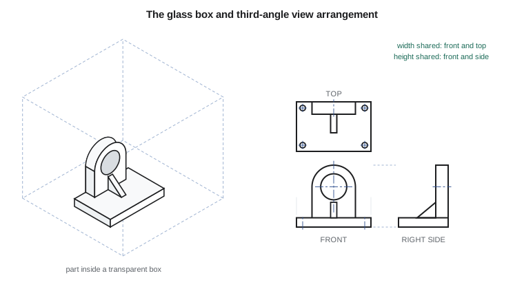
The unfolded arrangement fixes three relationships. The front and top views share width and are aligned vertically. The front and side views share height and are aligned horizontally. The top and side views share depth, which is why depth measured from the front edge of the top view equals depth measured from the front edge of the side view. A common way to carry depth from the top view to the side view is a 45° miter line: project horizontally from the top view to the miter line, then vertically down into the side view.
Most parts need only three views, and many need only two. A drawing should use the minimum number of views that defines the part completely and clearly. A turned shaft needs one view plus diameter symbols. A flat plate needs one view and a thickness note. The BB-210, with features in all three directions, needs three: front, top and right side.
First-angle projection
In first-angle projection the object sits between the viewer and the plane. Each view is projected through the object onto the plane behind it, so when the box is unfolded each view lands on the opposite side of the front view from where it was seen. The top view appears below the front view and the right-side view appears to the left of it. The views themselves are identical to third-angle views; only their positions differ.
The names come from descriptive geometry, which divides space into four quadrants, or angles, using a horizontal and a vertical plane. Placing the object in the first quadrant, in front of the vertical plane and above the horizontal plane, produces first-angle projection; placing it in the third quadrant, behind and below, produces third-angle projection. The second and fourth angles would make views overlap and are not used.
| View | Third-angle position | First-angle position |
|---|---|---|
| Top (plan) | Above the front view | Below the front view |
| Bottom | Below the front view | Above the front view |
| Right side | To the right of the front view | To the left of the front view |
| Left side | To the left of the front view | To the right of the front view |
| Rear | Beside the left or right side view, at the far end | Beside the left or right side view, at the far end |
Third-angle projection is standard in Canada, the United States and Australia under ASME and national practice. First-angle projection is standard in most of Europe, India and China, and ISO 5456 allows both. The two systems are defined by the same ISO standard, so neither is more correct; the risk lies entirely in a reader assuming the wrong one. That is why the projection symbol is mandatory in the title block of any drawing that might cross a border.
The projection symbol
The projection symbol shows a truncated cone, as if a short tapered plug, in two views: a front view showing the cone as a trapezoid, and an end view showing two concentric circles. In the third-angle symbol the circles are drawn to the right of the trapezoid, on the small end side, because in third angle the right-side view goes on the right. In the first-angle symbol the circles are on the left. A quick memory aid: in the third-angle symbol the end view sits next to the small end of the cone, exactly where you would see it from.
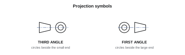
Owen's fix for the German customer was simple: the bracket drawing already showed the third-angle symbol, so Farah added the words THIRD ANGLE PROJECTION beside it, and the customer's receiving inspector added a note to their own system. Some companies that work in both markets draw a small pictorial on the sheet as well, because a pictorial cannot be misread in either system.
Choosing the front view
The front view is the most important view and should be chosen deliberately, not because it happens to be the side facing you. The best front view shows the most characteristic shape of the part, has the fewest hidden lines, and places the part in its natural, functional or manufacturing orientation. For the bracket, the front view looks along the bore axis, showing the circular bore, the rounded top of the upright and the base below. That view tells the reader at once what the part is.
Once the front view is chosen, the other views follow from it, and their choice depends on which features need to be shown. Select the side view with fewer hidden lines. Avoid views that duplicate information. Consider the sheet: a long part is usually drawn with its length horizontal, and views should fit without crowding the dimensions that will be added later.
Lines in orthographic views
Every edge, intersection and limit of a curved surface appears as a line in the views where it is visible or hidden. A visible edge is drawn as a thick continuous line. An edge behind material is drawn as a thin dashed hidden line. The axis of a hole or cylinder is drawn as a thin centre line, extending a few millimetres beyond the feature; in a circular view, two centre lines cross at the centre. When lines coincide, a precedence rule decides which one to draw: visible lines take precedence over hidden lines, and hidden lines over centre lines. Cutting-plane lines and break lines are placed where they are clearest.
A cylinder or a hole appears as a circle in the view looking along its axis and as a rectangle in the views perpendicular to it. Curved surfaces have no edge where they turn away from the viewer, but the limit of the surface, the outline, is drawn as a line. Fillets and rounds blend surfaces without a sharp edge; by convention, small runouts and tangent edges are shown or omitted according to company practice, and many drawings omit tangent edges to reduce clutter.
Normal, inclined and oblique surfaces
Reading views quickly depends on recognizing how a flat surface appears in each one. A normal surface is parallel to one of the principal planes; it appears true size in the view looking straight at it and as an edge, a single line, in the two adjacent views. An inclined surface is perpendicular to one principal plane but tilted to the other two; it appears as an edge in one view and foreshortened, smaller than true size but similar in shape, in the other two. An oblique surface is tilted to all three principal planes; it appears foreshortened in all three views and never as an edge. To see an inclined or oblique surface in true shape, you need an auxiliary view, the subject of lesson 6.
Worked problem
How an inclined surface appears
A wedge block is 60 mm long (x), 40 mm deep (y) and has a top surface that slopes from 30 mm high at the back to 10 mm high at the front. In which views is the sloping top surface true size, foreshortened or an edge?
Show solution
- The surface is perpendicular to the side (y–z) plane, because its slope is entirely in the y–z direction. In the right-side view it appears as an edge: a line from \((0, 10)\) to \((40, 30)\).
- Its true depth along the slope is \(\sqrt{40^2 + 20^2} = 44.72\) mm, so its true area is \(60 \times 44.72 = 2683\) mm².
- In the top view it appears as a 60 mm by 40 mm rectangle, 2400 mm², foreshortened by the factor \(40/44.72 = 0.894\).
- In the front view it appears as a 60 mm by 20 mm rectangle, 1200 mm², foreshortened by \(20/44.72 = 0.447\).
Answer: The sloping surface is an edge in the side view and foreshortened in the front and top views, so it is an inclined surface. Its angle, \(\arctan(20/40) = 26.6^\circ\), is seen true in the side view, the view in which the surface appears as an edge.
The program checks the same block automatically. It projects each face into the three views, compares the projected area with the true area, and labels the face as true size, foreshortened or an edge in each view.
import math

# A wedge block: 60 long (x), 40 deep (y), 30 high (z), with the top sloping
# from 30 mm high at the back (y = 40) down to 10 mm high at the front (y = 0).
V = {
    'A': (0, 0, 0), 'B': (60, 0, 0), 'C': (60, 40, 0), 'D': (0, 40, 0),
    'E': (0, 0, 10), 'F': (60, 0, 10), 'G': (60, 40, 30), 'H': (0, 40, 30),
}
faces = {'inclined top EFGH': 'EFGH', 'front ABFE': 'ABFE', 'right side BCGF': 'BCGF'}

# Each principal view drops one coordinate. Third-angle convention:
# front view looks along +y (sees x and z), top view looks down (x and y),
# right-side view looks along -x (sees y and z).
views = {'front': lambda p: (p[0], p[2]), 'top': lambda p: (p[0], p[1]), 'right': lambda p: (p[1], p[2])}

def area(pts):
    # shoelace formula for a planar polygon given in 2D
    s = 0
    for (x1, y1), (x2, y2) in zip(pts, pts[1:] + pts[:1]):
        s += x1 * y2 - x2 * y1
    return abs(s) / 2

def true_area(names):
    # Newell's method: area of a planar polygon in 3D from its vertices
    p = [V[n] for n in names]
    nx = ny = nz = 0.0
    for (x1, y1, z1), (x2, y2, z2) in zip(p, p[1:] + p[:1]):
        nx += (y1 - y2) * (z1 + z2); ny += (z1 - z2) * (x1 + x2); nz += (x1 - x2) * (y1 + y2)
    return math.sqrt(nx * nx + ny * ny + nz * nz) / 2

for fname, names in faces.items():
    print(f"{fname}: true area = {true_area(names):7.1f} mm^2")
    for vname, f in views.items():
        a = area([f(V[n]) for n in names])
        shape = 'edge (line)' if a < 1e-9 else ('true size' if abs(a - true_area(names)) < 1e-6 else 'foreshortened')
        print(f"   {vname:5s} view: projected area {a:7.1f}  -> {shape}")

# Slope of the inclined surface, seen true in the right-side view
rise, run = 30 - 10, 40
print(f"\nInclined top: rises {rise} mm over {run} mm, angle = {math.degrees(math.atan2(rise, run)):.1f} deg, "
f"true depth = {math.hypot(rise, run):.2f} mm")inclined top EFGH: true area = 2683.3 mm^2 front view: projected area 1200.0 -> foreshortened top view: projected area 2400.0 -> foreshortened right view: projected area 0.0 -> edge (line) front ABFE: true area = 600.0 mm^2 front view: projected area 600.0 -> true size top view: projected area 0.0 -> edge (line) right view: projected area 0.0 -> edge (line) right side BCGF: true area = 800.0 mm^2 front view: projected area 0.0 -> edge (line) top view: projected area 0.0 -> edge (line) right view: projected area 800.0 -> true size Inclined top: rises 20 mm over 40 mm, angle = 26.6 deg, true depth = 44.72 mm
Reading a set of views
Reading orthographic views is a matter of systematic correspondence. Pick a feature in one view, project it to the others using the shared dimensions, and identify what it must be. A circle in the front view that corresponds to two hidden lines in the top view is a hole running front to back. A line in the front view that corresponds to an area in the top view is a surface seen on edge. When two interpretations seem possible, the third view usually decides; that is one reason the third view exists even for fairly simple parts.
Experienced readers also use the principle of similar shapes: a surface that is not seen on edge appears with the same number of sides and the same general configuration in every view where it is not an edge. An L-shaped inclined surface appears as an L in both views where it is foreshortened. If the shapes do not match, either the reading is wrong or the drawing is.
Partial and removed views
Not every view needs to show the whole part. A partial view shows only the portion of the part needed, ending in a break line, which saves space and reduces hidden lines. A removed view is a view placed elsewhere on the sheet rather than in its projected position, identified by a viewing-direction arrow and a letter (VIEW A–A) and, if the scale differs, a scale note. A detail view enlarges a small region, circled and labelled on the parent view. These variations are all allowed by ASME Y14.3 and ISO 128, provided that the relationship to the parent view is clearly marked.
Common mistakes
MistakeAssuming every drawing uses third-angle projection.
InsteadCheck the projection symbol; first-angle drawings place views in opposite positions.
MistakeChoosing the front view because it is the side facing you.
InsteadChoose the view that best shows the characteristic shape with the fewest hidden lines.
MistakeDrawing more views than needed.
InsteadUse the minimum number of views that defines the part completely and clearly.
MistakeExpecting an inclined surface to appear true size in a principal view.
InsteadInclined surfaces are foreshortened in two principal views; only an auxiliary view shows them true size.
MistakeDrawing a centre line where a visible edge coincides with it.
InsteadFollow line precedence: visible over hidden over centre lines.
Summary and key terms
- Orthographic projection uses parallel projectors perpendicular to the projection plane, so features parallel to the plane appear true size.
- The glass box explains the arrangement of the six principal views; most parts need two or three.
- Front and top views share width, front and side views share height, top and side views share depth.
- Third-angle projection places views on the side from which they are seen; first-angle places them on the opposite side.
- The projection symbol in the title block states which system applies and must never be omitted on drawings that cross borders.
- Normal surfaces are true size in one view, inclined surfaces are an edge in one view, oblique surfaces are foreshortened in all three.
- Partial, removed and detail views reduce clutter when clearly referenced to the parent view.
- Orthographic projection
- Parallel projection with projectors perpendicular to the projection plane.
- Principal views
- The six views obtained from the glass box: front, top, right side, left side, bottom and rear.
- Third-angle projection
- The projection system in which each view is drawn on the side of the front view from which it is seen.
- First-angle projection
- The projection system in which each view is drawn on the side of the front view opposite to where it is seen.
- Projection symbol
- A truncated cone shown in two views that identifies the projection system.
- Inclined surface
- A flat surface perpendicular to one principal plane and tilted to the other two.
- Oblique surface
- A flat surface tilted to all three principal planes.
- Line precedence
- The rule that visible lines are drawn over hidden lines, and hidden lines over centre lines.
Practice problems
Work each problem on paper first, then reveal the answer to check.
In third-angle projection, where is the left-side view placed?
Show answer
To the left of the front view.
A drawing shows the top view below the front view. Which projection system is it?
Show answer
First-angle.
Which dimension do the top and right-side views share?
Show answer
Depth.
A hole appears as a circle in the top view. How does it appear in the front view?
Show answer
As hidden lines (a rectangle of dashed lines) with a centre line, unless the view is sectioned.
A surface appears as a line in the front view and as rectangles in the top and side views. What kind of surface is it?
Show answer
An inclined surface, perpendicular to the front plane.
Change the wedge in the program so the front height is 0. What is the slope angle and true depth?
Show answer
arctan(30/40) = 36.9° and a true depth of 50 mm.
Lesson quiz · 5 questions
Score 60% or more to complete this lesson.
Create a free account to save your progress, take quizzes and earn a certificate.