
MEC-260 · Lesson 5 of 12 · 23 min
Section views
The front view of the new BB-210 showed the bore as two concentric circles, the bore and its chamfer, and the side view showed a tangle of hidden lines: the bore, the counterbore for the seal, the grease passage, the rib behind the upright. Marco Rossi, the quality inspector who would eventually check the castings, looked at the side view and said he could not tell where the seal seat ended. Farah's answer was to cut the part in half on paper. A section view through the bore axis replaced the hidden lines with solid outlines, showed the wall thickness around the bore at a glance, and made the depth of the seal counterbore something that could be dimensioned. This lesson covers the types of sections, how they are drawn and the conventions that keep them readable.
Why sections
Hidden lines describe interior features, but only up to a point. When several interior features overlap, the hidden lines become impossible to interpret, and dimensioning to hidden lines is poor practice because it is easy to misread which edge a dimension belongs to. A section view solves the problem by imagining that a cutting plane slices through the part and that the material in front of the plane is removed. The view then shows the cut surface, filled with section lining, and everything visible behind the plane. Interior features become visible lines that can be dimensioned clearly.
Sections are especially valuable for castings, housings, pulleys, valves and any part with internal passages. They also show wall thickness, which matters for castings and moulded parts, where uneven walls cause shrinkage defects. A designer who sections a model early often discovers walls that are too thin, too thick or impossible to cast.
The cutting plane and the section view
The location of the cut is shown on an adjacent view by a cutting-plane line, a thick line of long dashes with short arrows at the ends pointing in the viewing direction, and a letter at each end: A–A for the first section, B–B for the next. The section view is labelled SECTION A–A. In third-angle projection the arrows point away from the section view, toward the material that remains, because the viewer looks at the cut face from the side the arrows point from. When a section lies in its normal projected position and the cutting plane is obvious, for example through the axis of symmetry, the cutting-plane line may be omitted, although many companies show it anyway.
In the section view, the cut surfaces are filled with section lining, also called hatching or cross-hatching: thin parallel lines, usually at 45°, evenly spaced about 1.5 to 3 mm apart depending on the size of the area. All cut surfaces of one part are hatched in the same direction and spacing, even if they are separated in the view, so that the reader recognizes them as the same piece. Adjacent parts in an assembly section are hatched in different directions or at different angles. Very thin sections, such as gaskets or sheet metal, may be filled solid black.
Visible edges behind the cutting plane are drawn as in any view. Hidden lines behind the plane are normally omitted in sections, because the purpose of the section is to remove them; they are added only if they are needed to define a feature that is not shown elsewhere.
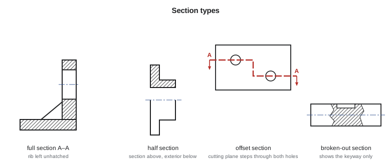
Types of sections
Standards recognize several types of sections, each suited to a particular geometry.
- Full section: the cutting plane passes completely through the part, usually along an axis of symmetry. The section replaces one principal view. It is the most common type and the one used for the BB-210 side view.
- Half section: for symmetric parts, the cutting planes remove one quarter, so that half the view shows the exterior and half shows the interior. A centre line, not a visible line, separates the two halves. Half sections are ideal for cylindrical parts such as flanges, pulleys and covers.
- Offset section: the cutting plane steps at right angles to pass through features that do not lie in one plane, such as holes at different locations. The steps are not shown in the section view; it is drawn as if the cut were flat.
- Broken-out section: a small irregular area is cut away to show one interior feature, bounded by a freehand break line. It avoids a full section when only one feature, such as a keyway or a tapped hole, needs to be shown.
- Revolved section: a cross-section is rotated 90° in place on the view, superimposed on it, to show the shape of a spoke, rib, arm or bar.
- Removed section: like a revolved section but drawn elsewhere on the sheet, labelled and often enlarged. It keeps the main view clear.
- Aligned section: the cutting plane bends to pass through angled features, such as spokes or holes on a bolt circle, and the angled portion is rotated into the plane of the paper before projection, so features appear at their true radius.
- Assembly section: an assembly cut to show how parts fit together, with each part hatched differently.
Conventions that break the rules on purpose
Several section conventions deliberately depart from true projection, because a true projection would mislead. The most important concerns thin features cut lengthwise. When a cutting plane passes along the length of a rib, web, spoke or gear tooth, the feature is not hatched. Hatching it would make the part look like a solid block, as if the rib were a thick wall. Instead, the rib is drawn with its outline and left without section lining, while the surrounding body is hatched. If the plane cuts across the rib, perpendicular to its length, the rib is hatched normally. The BB-210 section A–A cuts the front rib lengthwise, so the rib appears unhatched.
Similar conventions apply to standard parts in assembly sections. Shafts, bolts, nuts, pins, keys, rivets, washers and ball bearings' balls are not sectioned when the cutting plane passes along their axes, because they have no interior features and sectioning them adds confusion. They are drawn in full, unhatched. A section through a pump assembly shows the shaft whole, with the housing, bracket and bearing races around it hatched.
Aligned sections and the related practice of rotating features into the cutting plane also break strict projection. A flange with three holes on a bolt circle, sectioned through one hole, would show the other holes off-centre in a true projection; by convention, a hole is rotated into the plane so that the section shows it at its true radius, and the view becomes symmetric and easier to read. ASME Y14.3 describes these practices in detail.
Section A–A of the bracket
The cutting plane for section A–A of the BB-210 passes through the bore axis, at the middle of the part's length, and is viewed from the right. The section shows the base plate cut through its full depth, the upright wall cut through the bore, and the rib in front of the upright, unhatched because it is cut lengthwise. The bore itself appears as a gap through the upright, bounded by visible lines that show the seal counterbore and the chamfers. The rounded top of the upright, which follows a radius of 35 mm about the bore centre, appears as the top edge of the upright in the section.
Worked problem
Measuring material in a section
In section A–A, the base plate is 80 mm deep and 15 mm thick. The upright wall is 20 mm thick and runs from the top of the base at 15 mm up to 100 mm, interrupted by the 42 mm bore centred 65 mm above the bottom. The rib is a triangle with corners at (30, 15), (60, 15) and (60, 40), in (depth, height) coordinates. Find the hatched area and its centroid height.
Show solution
- Base: \(80 \times 15 = 1200\) mm², centroid at \(z = 7.5\) mm.
- The bore runs from \(65 - 21 = 44\) mm to \(65 + 21 = 86\) mm. Upright below the bore: \(20 \times (44 - 15) = 580\) mm² at \(z = 29.5\) mm. Upright above the bore: \(20 \times (100 - 86) = 280\) mm² at \(z = 93\) mm.
- The rib is cut lengthwise and is not hatched, so the hatched area is \(1200 + 580 + 280 = 2060\) mm².
- \[\bar{z} = \frac{1200(7.5) + 580(29.5) + 280(93)}{2060} = \frac{52\,150}{2060} = 25.3\ \text{mm}\]
Answer: The hatched area is 2060 mm² with its centroid 25.3 mm above the base. The rib adds another 375 mm² of material in the plane, but convention leaves it unhatched. The same calculation, used in reverse, lets a designer check that the wall around the bore is thick enough to carry the bearing load.
The program repeats the calculation for each region with the shoelace formula and also estimates how many hatch lines are needed across the base at a 3 mm spacing.
# Section A-A of the bracket: cutting plane through the bore axis (x = 60 mm).
# Coordinates are (y, z) in mm: y is depth front to back, z is height.
def region(poly):
    a = cy = cz = 0.0
    for (y1, z1), (y2, z2) in zip(poly, poly[1:] + poly[:1]):
        c = y1 * z2 - y2 * z1
        a += c; cy += (y1 + y2) * c; cz += (z1 + z2) * c
    a /= 2
    return abs(a), cy / (6 * a), cz / (6 * a)

parts = {
    'base plate':          [(0, 0), (80, 0), (80, 15), (0, 15)],
    'upright below bore':  [(60, 15), (80, 15), (80, 44), (60, 44)],
    'upright above bore':  [(60, 86), (80, 86), (80, 100), (60, 100)],
    'rib (cut lengthwise)': [(30, 15), (60, 15), (60, 40)],
}

def combine(names):
    A = sum(region(parts[n])[0] for n in names)
    Y = sum(region(parts[n])[0] * region(parts[n])[1] for n in names) / A
    Z = sum(region(parts[n])[0] * region(parts[n])[2] for n in names) / A
    return A, Y, Z

for n in parts:
    a, y, z = region(parts[n])
    print(f"{n:22s} area {a:7.1f} mm^2   centroid (y, z) = ({y:5.1f}, {z:5.1f})")

solid = ['base plate', 'upright below bore', 'upright above bore']
A, Y, Z = combine(solid)
print(f"\nHatched area in section A-A (rib left unhatched): {A:.0f} mm^2, centroid z = {Z:.1f} mm")
A2, Y2, Z2 = combine(solid + ['rib (cut lengthwise)'])
print(f"Total material in the cutting plane, including rib: {A2:.0f} mm^2, centroid z = {Z2:.1f} mm")

# Section lining: how many hatch lines for 45-degree lines at 3 mm spacing across the base?
import math
spacing = 3.0
diag = (80 + 15) * math.sin(math.radians(45))   # extent measured perpendicular to the lines
print(f"\nHatch lines across the base strip at {spacing} mm spacing: about {int(diag // spacing)}")base plate area 1200.0 mm^2 centroid (y, z) = ( 40.0, 7.5) upright below bore area 580.0 mm^2 centroid (y, z) = ( 70.0, 29.5) upright above bore area 280.0 mm^2 centroid (y, z) = ( 70.0, 93.0) rib (cut lengthwise) area 375.0 mm^2 centroid (y, z) = ( 50.0, 23.3) Hatched area in section A-A (rib left unhatched): 2060 mm^2, centroid z = 25.3 mm Total material in the cutting plane, including rib: 2435 mm^2, centroid z = 25.0 mm Hatch lines across the base strip at 3.0 mm spacing: about 22
Section lining symbols and materials
Older standards used different hatch patterns for different materials: cast iron, steel, brass, aluminium, rubber, wood. Modern ASME and ISO practice uses the general-purpose 45° pattern for all materials on detail drawings, because the material is specified in the title block and a pattern can never be as precise as a specification. Material-specific patterns are still used on assembly drawings, architectural drawings and some piping drawings, where they help distinguish parts quickly. If a company uses them, its drafting manual defines them.
Hatch lines should not be parallel or perpendicular to the main outline of the area, because they can be confused with the outline. If an area's outline runs at 45°, choose 30° or 60° instead. Avoid hatching that is so dense it prints as grey or so sparse that small areas contain only one line. Where a dimension or note must sit inside a hatched area, interrupt the hatching around the text.
Sections in 3D models
Modelling programs create sections instantly, and the result is exact. But the conventions above are not always applied automatically: a model section will happily hatch a rib cut lengthwise or a bolt on its axis. A drawing produced from the model must be checked and the section properties adjusted, for example by excluding ribs and fasteners from the section or by editing the hatch. Many programs allow standard parts to be flagged as not sectioned. Models also make dynamic sections easy, sliding a plane through a part to check wall thickness, and that habit is worth developing long before a drawing is needed.
Common mistakes
MistakeHatching a rib or web that the cutting plane passes along.
InsteadLeave ribs, webs and spokes cut lengthwise unhatched, and outline them.
MistakeSectioning shafts, bolts and pins cut along their axes.
InsteadDraw standard solid parts in full, unhatched, in assembly sections.
MistakeHatching separate regions of the same part in different directions.
InsteadUse the same angle and spacing for every cut surface of one part.
MistakeSeparating the two halves of a half section with a visible line.
InsteadUse a centre line between the sectioned and unsectioned halves.
MistakeShowing the steps of an offset section in the section view.
InsteadDraw the offset section as if the cut were flat; the steps appear only in the cutting-plane line.
Summary and key terms
- Section views replace confusing hidden lines with visible outlines by imagining a cut through the part.
- The cutting-plane line, with arrows and letters, shows where the cut is and which way it is viewed.
- Cut surfaces are hatched with thin, evenly spaced lines; all cut surfaces of one part share the same pattern.
- Full, half, offset, broken-out, revolved, removed, aligned and assembly sections each suit a particular geometry.
- Ribs, webs and spokes cut lengthwise, and shafts, fasteners and pins cut along their axes, are left unhatched.
- Hidden lines are normally omitted behind the cutting plane.
- Model-generated sections must be checked against drafting conventions before release.
- Cutting-plane line
- A thick dashed line with arrows showing the location and viewing direction of a section.
- Section lining
- Thin parallel lines filling a cut surface in a section view.
- Full section
- A section in which the cutting plane passes completely through the part.
- Half section
- A section of a symmetric part showing half exterior and half interior.
- Offset section
- A section whose cutting plane steps to pass through features not in one plane.
- Revolved section
- A cross-section rotated in place on a view.
- Removed section
- A cross-section drawn away from the view it belongs to, labelled and sometimes enlarged.
- Aligned section
- A section in which angled features are rotated into the cutting plane before projection.
Practice problems
Work each problem on paper first, then reveal the answer to check.
Which section type would you use for a cylindrical cover with symmetric interior features?
Show answer
A half section.
A cutting plane passes across a spoke of a handwheel, perpendicular to its length. Is the spoke hatched?
Show answer
Yes; only features cut lengthwise are left unhatched.
Why are hidden lines usually omitted from section views?
Show answer
The section exists to show the interior with visible lines; hidden lines add clutter.
In an assembly section of the pump, which items would appear unhatched?
Show answer
The shaft, bolts, nuts, keys, pins and bearing balls cut along their axes, and ribs cut lengthwise.
If the bore in the example were 50 mm instead of 42 mm, what would the hatched area be?
Show answer
The bore spans 40 to 90 mm: 1200 + 20 × 25 + 20 × 10 = 1900 mm².
Using the program, how does the centroid change when the rib is included?
Show answer
It falls slightly, from 25.3 mm to 25.0 mm, because the rib sits low in the section.
Lesson quiz · 5 questions
Score 60% or more to complete this lesson.
Create a free account to save your progress, take quizzes and earn a certificate.