
MEC-260 · Lesson 1 of 12 · 27 min
Engineering drawings and drawing standards
Owen Clarke's first job as a co-op student at Tidewater Pump Works in Moncton, New Brunswick, was not to design anything. Farah Siddiqui, the senior design engineer, gave him a printed drawing of a small cast part, the BB-210 bearing bracket, and asked him to find three things wrong with it before lunch. The bracket holds the outboard bearing of a centrifugal pump shaft. It is cast in aluminium, machined on a few surfaces, and bolted to the pump base with four screws. The drawing looked complete: three views, a pictorial, dozens of dimensions, a title block. Owen found two problems by noon. The third, a missing tolerance on the bearing bore, took him until the afternoon, and Farah told him that the machine shop had found it the hard way the year before, after scrapping forty castings. This course follows the BB-210 from a freehand sketch to a released drawing package and a 3D model, and it teaches the language that lets an engineer describe a part so exactly that someone else can make and inspect it without asking a single question.
Why engineering drawings exist
An engineering drawing is a legal and technical document, not a picture. It defines the geometry of a part, the size and location of every feature, how much each may vary, the material, the finish and any special processing. The people who use it are rarely in the room with the designer. A foundry in another province or state makes the casting; a machine shop machines it; an inspector in receiving checks it; a buyer compares quotes; a field technician orders a replacement fifteen years later. Each of them reads the drawing as the complete statement of what was ordered. If the drawing is silent, they will fill the gap with their own assumption, and that assumption may not match the designer's intent.
This is why companies treat drawings as controlled records. The drawing, or the model that replaces it, is the basis of the purchase contract with a supplier. If a part meets the drawing but does not work, the problem belongs to the designer. If the part fails the drawing, the supplier owns it, even if the part would have worked. Engineers therefore learn to write drawings that are complete (every feature fully defined), unambiguous (only one reasonable reading) and functional (the requirements express what the part must do, not just how one machinist might happen to make it).
Graphics also matter long before a drawing is released. Engineers sketch to think, to explain an idea to a colleague, to record a measurement in the field, and to check whether a design fits. A clear sketch in a design review can save a week of modelling. Much of the skill taught in this course, especially visualizing a three-dimensional object from flat views and the reverse, is the same skill whether you use a pencil, a 3D modelling program or a tablet.
Kinds of technical drawings
A complete product needs several kinds of drawings, each with a different job.
- A detail drawing defines one part completely: views, dimensions, tolerances, material, finish and notes. The BB-210 drawing is a detail drawing.
- An assembly drawing shows how parts go together, identifies each one with a balloon (a numbered circle) and lists them in a parts list or bill of materials. It usually carries only the dimensions needed for assembly, such as overall size or a required gap.
- A layout or design drawing is a working drawing that engineers use to develop a mechanism, check clearances and fix key dimensions before detailing the parts.
- Schematic and diagrammatic drawings show function rather than shape: hydraulic circuits, piping and instrumentation diagrams, wiring diagrams.
- Installation, casting, weldment and machining drawings show a part at a particular stage of manufacture. A casting drawing, for example, shows the raw casting with its draft angles and machining allowances; the machining drawing shows the finished part.
In industry these drawings are linked. The BB-210 has a casting drawing for the foundry, a machining drawing for the shop, and appears as item 6 on the pump assembly drawing. A change to one may force changes to the others, which is why lesson 12 spends time on revision control.
Standards: the grammar of drawings
A drawing can only be read unambiguously if writer and reader follow the same rules. Those rules are published as standards. In North America, the ASME Y14 series is the most widely used family. ASME Y14.100 covers general engineering drawing practices; Y14.1 and Y14.1M cover sheet sizes and formats; Y14.2 covers line conventions and lettering; Y14.3 covers views, including sections; Y14.5 covers dimensioning and tolerancing; Y14.41 covers digital product definition, meaning models that carry dimensions and tolerances directly. The current dimensioning and tolerancing standard is ASME Y14.5-2018, reaffirmed in 2024, and the course uses it throughout.
Internationally, ISO publishes an equivalent but not identical set. ISO 128 covers the general principles of presentation, including line types and views; ISO 129 covers dimensioning; ISO 5456 covers projection methods; ISO 286 covers limits and fits; and the ISO geometrical product specification (GPS) system, including ISO 1101 for geometric tolerancing, covers tolerances of form, orientation, location and runout. ASME and ISO symbols look almost the same, but some rules differ in ways that matter, particularly the default relationship between size and form. Lesson 9 returns to that difference.
Canadian practice sits between the two. CSA published its own drawing standards, the B78 series, including CAN/CSA-B78.2 on dimensioning and tolerancing, which was last reaffirmed in 2002 and is rarely cited today. In practice, most Canadian manufacturers follow ASME Y14.5 when their customers are in North America, and ISO GPS when they supply European or Asian companies. Tidewater ships pumps to both markets, so Farah keeps a short company standard that states which standard governs each drawing, and every title block names it. That single line removes a whole class of argument about what a symbol means.
Companies add their own standards on top of the national ones: preferred materials and finishes, standard notes, title block layout, numbering schemes, approved fasteners. A new engineer should read the company drafting manual early. It answers questions such as whether general tolerances appear in the title block, how revisions are lettered and who must sign before release.
Units and the inch–metric question
Drawings are either metric or inch, and a drawing should say which. Metric drawings dimension in millimetres without writing the unit after each number: a dimension of 42 means 42 mm. Inch drawings dimension in decimal inches, also without the unit mark, so 1.654 means 1.654 in. Fractions such as 3/8 appear only for nominal sizes of standard items like threads, drill sizes or lumber, not for toleranced dimensions. A note such as UNLESS OTHERWISE SPECIFIED, DIMENSIONS ARE IN MILLIMETRES in the title block removes any doubt. Dual dimensioning, which shows both units, is discouraged because it doubles the chance of a conversion error and makes the drawing cluttered.
Canadian industry is mostly metric for new designs, but many machines, fasteners and raw materials still come in inch sizes because of the close link with US suppliers. Tidewater's pumps are designed in millimetres, but the bracket's mounting holes are positioned to suit an inch-pattern pump base that a large customer insisted on. Owen learned to check the units note before reading any number.
The drawing sheet and the title block
Drawings are made on standard sheet sizes so that they can be printed, filed and scaled consistently. ISO 216 defines the A series, in which A0 has an area of one square metre and each smaller size is half the previous one, keeping the ratio of the sides at \(\sqrt{2}\). ASME Y14.1 defines inch sizes A to E, which are based on letter-size paper and do not keep a constant ratio. Even when drawings live mostly on screens, the sheet size still controls how much detail fits at a legible scale, and suppliers still print them.
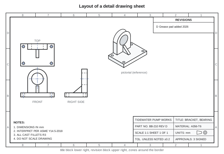
Every sheet has a border, and most have zone markings, letters along one side and numbers along the other, like a map grid. A checker can then write that the problem is in zone C3, and anyone can find it. The title block, usually in the lower right corner, holds the information that identifies and controls the drawing.
- Company name and drawing title, usually written noun first, such as BRACKET, BEARING.
- Drawing number and part number, which are often the same, and the sheet number if there is more than one sheet.
- Revision letter, with the history recorded in a separate revision block.
- Scale, units, and the projection symbol showing first- or third-angle projection (lesson 3).
- Material and finish, or a reference to a separate specification.
- General tolerances that apply to any dimension without its own tolerance.
- The governing standards, such as ASME Y14.5-2018, and approval signatures or electronic approvals with dates.
Owen's first find on the BB-210 drawing was in the title block. The scale said 1:1, but the views had been printed on a smaller sheet, so anyone who measured the print with a ruler would get wrong values. That is why drawings carry the note DO NOT SCALE DRAWING: dimensions are read from the numbers, never measured from the print. Paper shrinks, printers rescale, and screens zoom. The scale tells you only the relationship between the views and the real part when the drawing was made.
Scale
A drawing scale is written as drawing size to actual size. Full scale is 1:1; 1:2 means the drawing is half size; 2:1 means it is twice size. Metric drawings use preferred scales from ISO 5455: enlargement scales of 2:1, 5:1, 10:1 and so on, and reduction scales of 1:2, 1:5, 1:10, 1:20, 1:50 and 1:100. Inch drawings use full, half and quarter size for parts, and architectural or civil scales for buildings and sites. A small detail can be enlarged in a detail view at a different scale from the main views, and its scale must then be stated under it.
Worked problem
Choosing a sheet and scale
The three views of the BB-210, with spacing for dimensions, occupy about 260 mm by 170 mm at full size. The company leaves a 20 mm border on all sides and a 60 mm strip along the bottom for the title block and notes. Which A-series sheet is the smallest that holds the views at 1:1, and which is needed at 2:1?
Show solution
- A3 landscape is 420 mm by 297 mm. The usable width is \(420 - 2 \times 20 = 380\) mm and the usable height is \(297 - 2 \times 20 - 60 = 197\) mm.
- At 1:1 the views need 260 mm by 170 mm. Since \(260 \le 380\) and \(170 \le 197\), A3 is large enough. A4 landscape (297 mm by 210 mm) gives only \(257 \times 110\) mm, which is too small.
- At 2:1 the views need 520 mm by 340 mm. A2 (594 mm by 420 mm) gives \(554 \times 320\) mm usable: too short. A1 (841 mm by 594 mm) gives \(801 \times 494\) mm, which fits.
Answer: Use A3 at 1:1. Doubling the scale quadruples the area needed and pushes the drawing up two sheet sizes, which is why designers enlarge only the details that need it rather than the whole drawing.
The program below repeats the calculation. It derives the A-series sizes from the one-square-metre rule, lists the ANSI inch sizes for comparison, and finds the smallest sheet that holds a given set of views.
import math

# ISO 216 A-series sheets: A0 has an area of 1 m^2 and sides in the ratio sqrt(2).
def a_series(n):
    w = round(1000 / 2 ** 0.25)     # short side of A0: 841 mm
    h = round(1000 * 2 ** 0.25)     # long side of A0: 1189 mm
    for _ in range(n):
        w, h = h // 2, w            # halve the long side, rounding down to whole mm
    return w, h

print("ISO A-series sheets (mm), from A0 = 1 m^2 and the sqrt(2) ratio:")
for n in range(5):
    w, h = a_series(n)
    print(f"  A{n}: {w:4d} x {h:4d}   area = {w*h/1e6:.3f} m^2")

# ANSI Y14.1 inch sheets do not keep one aspect ratio.
ansi = {"A": (8.5, 11), "B": (11, 17), "C": (17, 22), "D": (22, 34), "E": (34, 44)}
print("\nANSI inch sheets:")
for k, (w, h) in ansi.items():
    print(f"  {k}: {w:>4} x {h:>4} in   ratio = {h/w:.3f}   ({w*25.4:.0f} x {h*25.4:.0f} mm)")

# Which sheet holds a drawing at a given scale? Bracket views need about 260 x 170 mm at 1:1.
need = (260, 170)
for scale in (1, 2):
    w, h = need[0] * scale, need[1] * scale
    for n in range(4, -1, -1):
        sw, sh = a_series(n)
        # allow 20 mm border and a 60 mm title block strip along the bottom
        if h <= sw - 40 - 60 and w <= sh - 40:
            print(f"\nViews at {scale}:1 need {w} x {h} mm: smallest sheet that fits is A{n} landscape")
breakISO A-series sheets (mm), from A0 = 1 m^2 and the sqrt(2) ratio: A0: 841 x 1189 area = 1.000 m^2 A1: 594 x 841 area = 0.500 m^2 A2: 420 x 594 area = 0.249 m^2 A3: 297 x 420 area = 0.125 m^2 A4: 210 x 297 area = 0.062 m^2 ANSI inch sheets: A: 8.5 x 11 in ratio = 1.294 (216 x 279 mm) B: 11 x 17 in ratio = 1.545 (279 x 432 mm) C: 17 x 22 in ratio = 1.294 (432 x 559 mm) D: 22 x 34 in ratio = 1.545 (559 x 864 mm) E: 34 x 44 in ratio = 1.294 (864 x 1118 mm) Views at 1:1 need 260 x 170 mm: smallest sheet that fits is A3 landscape Views at 2:1 need 520 x 340 mm: smallest sheet that fits is A1 landscape
Lines and lettering
Drawings use a small set of line types, each with a meaning. ASME Y14.2 and ISO 128 define them; the names differ slightly but the ideas are the same. Visible lines (thick, continuous) show edges you can see. Hidden lines (thin, dashed) show edges behind the surface. Centre lines (thin, long and short dashes) mark axes of symmetry and the centres of holes. Dimension and extension lines (thin, continuous) carry dimensions. Cutting-plane lines (thick, with long dashes and arrows) show where a section is taken. Section lining (thin, evenly spaced) shows cut material. Phantom lines (thin, long dash and two short dashes) show alternate positions, adjacent parts or repeated detail. Two line thicknesses are usual: thick lines about 0.6 or 0.7 mm and thin lines about 0.35 mm, in a ratio of about two to one.
| Line type | Appearance | Weight | Typical use |
|---|---|---|---|
| Visible (object) | Continuous | Thick | Edges and outlines that can be seen |
| Hidden | Short dashes | Thin | Edges behind a surface |
| Centre | Long and short dashes | Thin | Axes, hole centres, paths of motion |
| Dimension and extension | Continuous with arrowheads | Thin | Showing size and location |
| Leader | Continuous with one arrowhead or dot | Thin | Pointing to notes and callouts |
| Cutting plane | Long dashes with arrows | Thick | Where a section is taken and which way it is viewed |
| Section lining | Evenly spaced thin lines | Thin | Surfaces cut by a section plane |
| Phantom | Long dash, two short dashes | Thin | Adjacent parts, alternate positions, repeated features |
| Break | Freehand or zig-zag | Thin or thick | Shortening a long part or showing a partial view |
Lettering on drawings uses a plain sans-serif style, almost always upper case, so that every character is unmistakable when printed small or photocopied. A common height is 3 to 3.5 mm for notes and dimensions and 5 to 7 mm for titles. The letter O and the number 0, and the letter I and the number 1, must never be confused, which is one reason for the plain style. Computer-aided drafting handles lettering automatically, but engineers still letter by hand on sketches, field notes and markups, and neat lettering is a professional courtesy to everyone who reads them.
From paper drawings to model-based definition
Most new parts start as a 3D model in a parametric modelling program, and the 2D drawing is produced from the model. For many companies the drawing is still the controlling document: the model is used to make the drawing and to program machines, but the drawing governs when there is a disagreement. A growing number of companies use model-based definition (MBD), in which the annotated model itself carries the dimensions, tolerances and notes and is the controlling document, as described in ASME Y14.41. Some use a mix: a simplified drawing that carries only critical tolerances and notes, with a reference to the model for everything else. Whatever the format, the content is the same, and so are the skills. You still need projection, sections, dimensioning and geometric tolerancing to define a part completely, and you still need to read 2D drawings, because decades of existing parts are defined by them.
Owen's three findings
By the end of his first day, Owen had listed three problems with the old BB-210 drawing. The scale in the title block did not match the printed sheet, which only mattered because someone in the shop had scaled the print. The general notes referred to a company standard that had been withdrawn. And the bearing bore, the most important feature on the part, had a size of 42 with no tolerance, so it fell under the title block general tolerance of plus or minus 0.2 mm, far too loose for a bearing that needs a few hundredths of a millimetre. The rest of the course explains how to avoid each of these problems and how to write a drawing that a supplier can follow without guessing.
Common mistakes
MistakeMeasuring a print with a ruler to find a missing dimension.
InsteadNever scale a drawing; ask for the dimension or check the model, because prints are often resized.
MistakeAssuming a drawing is metric or inch from the size of the numbers.
InsteadRead the units note in the title block before reading any dimension.
MistakeLeaving a critical feature with no tolerance of its own.
InsteadAny dimension without a tolerance takes the general tolerance, which may be far too loose; tolerance critical features directly.
MistakeTreating ASME and ISO drawings as interchangeable.
InsteadThe symbols look alike but some default rules differ; the drawing must state which standard governs.
MistakeUsing line weights and types loosely.
InsteadEach line type carries a meaning; hidden, centre and visible lines must be distinguishable.
Summary and key terms
- An engineering drawing is a controlled technical and legal document that completely defines a part for people who cannot ask the designer.
- Detail, assembly, layout, schematic and process drawings each serve a different purpose and are linked by part numbers.
- ASME Y14 standards dominate in North America; ISO GPS standards are used internationally; the drawing must name its governing standard.
- Metric drawings dimension in millimetres and inch drawings in decimal inches, without unit marks on each dimension.
- The title block identifies the part, revision, scale, units, projection, material, general tolerances and approvals.
- Drawings are never scaled; the stated scale relates the views to the part only as drawn.
- Standard line types and weights carry meaning, and lettering is plain and upper case.
- Model-based definition moves dimensions and tolerances into the 3D model, but the underlying skills are the same.
- Detail drawing
- A drawing that completely defines a single part for manufacture and inspection.
- Assembly drawing
- A drawing that shows how parts fit together and lists them in a bill of materials.
- Title block
- The area of a drawing sheet that identifies and controls the drawing.
- Revision block
- The table recording each change to a drawing, with its letter, description, date and approval.
- General tolerance
- The tolerance that applies to any dimension not given its own tolerance.
- Drawing scale
- The ratio of drawing size to actual size, such as 1:2 or 2:1.
- Model-based definition
- The practice of using an annotated 3D model, rather than a drawing, as the controlling definition of a part.
- Zone
- A lettered and numbered region of the drawing border used to locate features on the sheet.
Practice problems
Work each problem on paper first, then reveal the answer to check.
An A2 sheet is folded in half twice. What size results?
Show answer
A4: each fold halves the long side, A2 → A3 → A4.
Why does a drawing note say DO NOT SCALE DRAWING?
Show answer
Prints may be resized and paper changes size; only the dimensions are reliable.
Name four items found in a title block.
Show answer
Any four of: title, part number, revision, scale, units, projection symbol, material, general tolerance, governing standard, approvals.
What is the difference between a casting drawing and a machining drawing of the same part?
Show answer
The casting drawing shows the raw casting with draft and machining allowances; the machining drawing shows the finished, machined geometry.
A metric drawing shows a dimension of 12.5. What does it mean?
Show answer
12.5 mm; metric drawings omit the unit on each dimension.
Run the program with views of 300 mm by 200 mm. Which sheet holds them at 1:1?
Show answer
A3 no longer fits the 200 mm height (197 mm usable), so A2 is needed.
Lesson quiz · 5 questions
Score 60% or more to complete this lesson.
Create a free account to save your progress, take quizzes and earn a certificate.