
MEC-260 · Lesson 4 of 12 · 23 min
Pictorial views: isometric, oblique and perspective
Tidewater's service manual for the pump shows the BB-210 in a single picture: an isometric view of the bracket with the bearing, the grease fitting and the four mounting screws, each labelled with a balloon. The field technicians who use the manual are skilled, but they are not drafters, and three orthographic views would slow them down. Farah's rule is that orthographic views define a part and pictorial views explain it. This lesson covers the pictorial systems, how they are constructed, and when each one is the right choice.
Pictorial projection systems
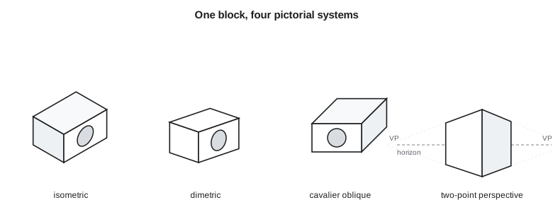
A pictorial view shows an object's three dimensions in one view. There are three families. Axonometric projections use parallel projectors perpendicular to the picture plane, like orthographic views, but the object is turned and tilted so that three faces are seen at once. Oblique projections use parallel projectors that strike the picture plane at an angle, so one face of the object can stay parallel to the plane and appear in true shape. Perspective projections use projectors that converge at a single point, the viewer's eye, which produces the convergence of parallel lines that we see in photographs.
Each family trades realism against measurability. Axonometric and oblique views keep parallel lines parallel and allow measurement along certain directions, so they suit technical illustration, assembly instructions and quick design sketches. Perspective views look most natural and suit architecture, product presentation and industrial design, but measurements cannot be taken from them directly. Most 3D modelling programs can display any of these at the click of a button; knowing what each one shows and hides is what lets you choose wisely.
Axonometric projection
In axonometric projection the object is rotated about a vertical axis and tilted toward the viewer, and then projected orthographically. The three principal axes of the object appear on the paper as three lines meeting at a point, and lengths along each axis are shortened by a factor that depends on its angle to the picture plane. The subtypes are named for how many of those factors are equal.
- Isometric: all three axes are foreshortened equally and appear 120° apart. This happens when the object is rotated 45° and tilted about 35.26°, so that a cube's diagonal points straight at the viewer.
- Dimetric: two axes are foreshortened equally and the third differently. The view can emphasize the top or the front of an object.
- Trimetric: all three axes are foreshortened differently. It gives the most freedom to show an object well, at the cost of three different scales.
Isometric is by far the most used because one scale serves all three axes. In true isometric projection every axis is foreshortened by \(\sqrt{2/3} \approx 0.816\). Drafters almost always ignore this and draw lengths along the axes at full size. The result, an isometric drawing rather than an isometric projection, is about 22 percent larger than the true projection but identical in shape, and it can be measured directly with an ordinary scale. Modelling programs usually display a true projection, so an isometric view printed from a model will measure smaller than a hand-drawn isometric drawing of the same part.
Constructing isometric drawings
The box method is the standard construction. Draw the isometric envelope of the part using its overall length, width and height along the three axes, then cut away or add features by measuring along lines parallel to the axes. Any edge parallel to a principal axis is an isometric line and can be measured at full length. Any other edge is a non-isometric line: locate its two end points by measuring along isometric lines, then join them. Angles are not true in isometric; a 90° corner on a face may appear as 60° or 120°, so angled features must be built from their end points, never with a protractor.
Hidden lines are normally omitted from pictorials, because they make the view confusing and the reader can usually infer what is hidden. If a hidden feature matters, show it with a section or a cutaway instead. Centre lines are drawn only where they help, for example to locate holes for an assembly instruction.
Circles and arcs in isometric
A circle in any of the three principal faces appears in isometric as an ellipse. The ellipse's major axis is perpendicular to the axis of the circle, and its minor axis is parallel to it. On a hand drawing the ellipse is built inside the isometric square, the rhombus that encloses the circle, touching the midpoints of the four sides. The four-centre method approximates it with four circular arcs: draw perpendiculars from the midpoints of the rhombus's sides; they meet at four points, which become the centres of the arcs. The approximation is close enough for most illustrations, and ellipse templates or software give exact ellipses when needed.
Worked problem
A bore on an isometric face
The BB-210 bore is 42 mm in diameter. Find the size of the ellipse that represents it in a true isometric projection and in an isometric drawing drawn at full size along the axes.
Show solution
- In the true projection the major axis equals the true diameter, because the diameter perpendicular to the circle's axis lies parallel to the picture plane: 42 mm.
- The minor axis is shortened by the sine of the angle between the line of sight and the face, \(\sin 35.26^\circ = 0.577\): \(42 \times 0.577 = 24.2\) mm.
- An isometric drawing enlarges everything by 1.2247, giving \(42 \times 1.2247 = 51.4\) mm by \(24.2 \times 1.2247 = 29.7\) mm.
Answer: The ellipse is 42.0 by 24.2 mm in a true projection and 51.4 by 29.7 mm in a full-size isometric drawing. In both, the ratio of minor to major axis is 0.577, which is why isometric ellipse templates are labelled as 35° ellipses.
The program generalizes the calculation. It computes the axis scales and drawing angles for an isometric view and for one example each of dimetric and trimetric views, then repeats the bore calculation.
import math

def axonometric(rot_z_deg, tilt_x_deg):
    """Rotate the object about the vertical axis, then tilt it toward the viewer,
    and project onto the picture plane. Returns the foreshortening factor of the
    x, y and z axes and the angle each projected axis makes with the horizontal."""
    a, b = math.radians(rot_z_deg), math.radians(tilt_x_deg)
    axes = {'x': (1, 0, 0), 'y': (0, 1, 0), 'z': (0, 0, 1)}
    out = {}
    for k, (x, y, z) in axes.items():
        # rotate about z
        x1, y1, z1 = x * math.cos(a) - y * math.sin(a), x * math.sin(a) + y * math.cos(a), z
        # tilt about the horizontal screen axis; view along the depth axis y
        y2, z2 = y1 * math.cos(b) - z1 * math.sin(b), y1 * math.sin(b) + z1 * math.cos(b)
        u, v = x1, z2                         # picture-plane coordinates
        out[k] = (math.hypot(u, v), math.degrees(math.atan2(v, u)))
    return out

cases = {
    'isometric': (45, math.degrees(math.atan(1 / math.sqrt(2)))),
    'dimetric (one example)': (45, 20),
    'trimetric (one example)': (30, 25),
}
for name, (rz, tx) in cases.items():
    r = axonometric(rz, tx)
    print(f"{name}: rotation {rz:.1f} deg, tilt {tx:.2f} deg")
    for k in 'xyz':
        f, ang = r[k]
        print(f"   {k} axis: scale {f:.4f}, drawn at {ang:7.2f} deg")

iso = 1 / math.sqrt(1.5)
print(f"\nIsometric projection scale = sqrt(2/3) = {iso:.4f}")
print(f"Isometric drawing enlarges the projection by 1/{iso:.4f} = {1/iso:.4f}")

# A 42 mm bore drawn on an isometric face
D = 42
major_proj, minor_proj = D, D * math.tan(math.radians(30))
print(f"\n42 mm circle, true isometric projection: ellipse {major_proj:.1f} x {minor_proj:.1f} mm")
print(f"Same circle in an isometric drawing (full-size axes): ellipse {major_proj/iso:.1f} x {minor_proj/iso:.1f} mm")
print(f"Minor/major ratio = {minor_proj/major_proj:.3f}, so the ellipse angle is {math.degrees(math.asin(minor_proj/major_proj)):.2f} deg")isometric: rotation 45.0 deg, tilt 35.26 deg x axis: scale 0.8165, drawn at 30.00 deg y axis: scale 0.8165, drawn at 150.00 deg z axis: scale 0.8165, drawn at 90.00 deg dimetric (one example): rotation 45.0 deg, tilt 20.00 deg x axis: scale 0.7473, drawn at 18.88 deg y axis: scale 0.7473, drawn at 161.12 deg z axis: scale 0.9397, drawn at 90.00 deg trimetric (one example): rotation 30.0 deg, tilt 25.00 deg x axis: scale 0.8914, drawn at 13.71 deg y axis: scale 0.6196, drawn at 143.80 deg z axis: scale 0.9063, drawn at 90.00 deg Isometric projection scale = sqrt(2/3) = 0.8165 Isometric drawing enlarges the projection by 1/0.8165 = 1.2247 42 mm circle, true isometric projection: ellipse 42.0 x 24.2 mm Same circle in an isometric drawing (full-size axes): ellipse 51.4 x 29.7 mm Minor/major ratio = 0.577, so the ellipse angle is 35.26 deg
Oblique projection
Oblique projection keeps one face of the object parallel to the picture plane, so that face appears in true size and shape, and draws the receding depth axis at an angle, usually 30° or 45°. Circles on the front face stay circles, which makes oblique views easy to draw for parts with many circular features in one plane, such as flanges, gears and the front of the bracket. The depth axis can be drawn at three common scales.
- Cavalier oblique draws depth at full scale. It is easy to measure but makes deep objects look too deep.
- Cabinet oblique draws depth at half scale. It looks more natural and is the most common choice for furniture and machinery illustration.
- General oblique uses any scale between half and full.
To get the best oblique view, place the face with the most circles or the most complex outline parallel to the picture plane, and put the longest dimension of the part parallel to the plane as well, so that the distorted depth axis is short. Oblique views have a strong distortion for deep parts, which is why they suit flat or shallow objects.
Perspective projection
Perspective projection mimics how the eye and a camera see. Parallel lines that recede from the viewer converge toward vanishing points on the horizon line, the line at the viewer's eye level. In one-point perspective one face of the object is parallel to the picture plane and the receding lines converge to one vanishing point; it suits interiors and long corridors. In two-point perspective the vertical edges stay vertical and the two sets of horizontal edges converge to two vanishing points; it is the standard for buildings and products. In three-point perspective vertical edges converge too, which suits views looking steeply up at a tall building or down on an object.
Perspective is not used for manufacturing because sizes vary with distance from the viewer. It is valuable for presenting designs to clients, management or the public, and many design reviews begin with a perspective rendering before anyone looks at a drawing. Modelling programs switch between parallel and perspective display with a single setting; engineers usually work in parallel views and switch to perspective only for presentation.
| System | Projectors | Measurable along | Circles on front face | Typical use |
|---|---|---|---|---|
| Isometric | Parallel, perpendicular to plane | All three axes (one scale) | Ellipses | Assembly instructions, manuals, sketches |
| Dimetric / trimetric | Parallel, perpendicular to plane | Axes, with two or three scales | Ellipses | Technical illustration where isometric looks awkward |
| Oblique | Parallel, inclined to plane | Front face true; depth at chosen scale | True circles | Flat parts with circular features |
| Perspective | Converging to the eye | Not directly | Ellipses, varying with position | Presentation, architecture, industrial design |
Exploded and cutaway pictorials
Two variations of pictorial views appear constantly in engineering. An exploded view separates the parts of an assembly along their assembly axes, with thin centre lines showing how they go together. It is the standard illustration for assembly instructions and parts catalogues, and lesson 12 uses one for the pump bearing assembly. A cutaway view removes part of an object, as if sliced, to reveal interior features, combining the clarity of a section with the realism of a pictorial. Modelling programs generate both easily, and both are often more effective than a set of orthographic views for anyone who is not reading the drawing to make the part.
Pictorial views on detail drawings are usually small, unscaled and labelled FOR REFERENCE ONLY or similar, so that no one tries to measure them. Their job is to help the reader orient the orthographic views. Owen added one to the new BB-210 drawing, in the upper right corner, and the machine shop supervisor told him it was the first thing everyone looked at.
Choosing a pictorial
The best pictorial is the one that shows the important features most clearly with the least distortion. Choose the viewing direction so that the key features face the viewer: for the bracket, the bore and the rib should be visible. Avoid views in which an important edge lines up with another or a face is seen almost on edge. For isometric views, check that the part's diagonal does not point straight at the viewer, which can make a corner and the opposite corner coincide and produce a confusing flat look. If the isometric looks awkward, a dimetric view usually fixes it.
Common mistakes
MistakeMeasuring angles with a protractor on an isometric drawing.
InsteadAngles are distorted in isometric; locate the end points of angled edges along isometric lines.
MistakeDrawing a circle on an isometric face as a circle.
InsteadCircles on isometric faces are ellipses with the minor axis along the circle's axis.
MistakeExpecting a modelling program's isometric view to match a hand-drawn isometric drawing in size.
InsteadThe program shows a true projection, about 0.816 of the hand-drawn full-size isometric drawing.
MistakeUsing cavalier oblique for a deep part.
InsteadUse cabinet oblique, or place the longest dimension parallel to the picture plane.
MistakeDimensioning a pictorial view for manufacture.
InsteadPictorials illustrate; orthographic views and annotated models define the part.
Summary and key terms
- Pictorial views show three dimensions in one view and are used to explain, not usually to define, a part.
- Axonometric projections are isometric, dimetric or trimetric depending on how many axis scales are equal.
- Isometric projection foreshortens all axes by 0.816; isometric drawings use full size along the axes.
- Isometric circles are ellipses with a minor-to-major ratio of 0.577 and the minor axis along the circle's axis.
- Oblique views keep the front face true shape; cabinet oblique halves the depth to reduce distortion.
- Perspective views converge parallel lines to vanishing points and are used for presentation.
- Exploded and cutaway pictorials are standard for assembly instructions and service documents.
- Axonometric projection
- Orthographic projection of an object rotated so that three faces are visible.
- Isometric drawing
- An isometric pictorial drawn at full size along the three axes.
- Four-centre ellipse
- An approximate isometric ellipse built from four circular arcs.
- Oblique projection
- Parallel projection with projectors inclined to the picture plane, keeping one face true shape.
- Cabinet oblique
- Oblique projection with the depth axis drawn at half scale.
- Vanishing point
- The point toward which parallel receding lines converge in perspective.
- Exploded view
- A pictorial of an assembly with parts separated along their assembly axes.
Practice problems
Work each problem on paper first, then reveal the answer to check.
A 100 mm edge is drawn in an isometric drawing at full size. How long is it in a true isometric projection?
Show answer
81.6 mm.
Why are oblique views good for flanges?
Show answer
The face with the bolt circle and bore stays true shape, so circles remain circles.
In cabinet oblique, how is a 60 mm depth drawn?
Show answer
30 mm along the receding axis.
What is the minor axis of a 30 mm circle in an isometric drawing at full size along the axes?
Show answer
30 × 0.577 × 1.2247 = 21.2 mm.
Which pictorial system would you use for a client presentation of a new pump skid?
Show answer
Perspective, usually two-point, for a natural appearance.
In the program, what tilt angle makes the x and z scales equal when the rotation is 45°?
Show answer
The isometric tilt of 35.26°, where all three scales are 0.8165.
Lesson quiz · 5 questions
Score 60% or more to complete this lesson.
Create a free account to save your progress, take quizzes and earn a certificate.