
MEC-260 · Lesson 2 of 12 · 25 min
Freehand sketching and visualization
Before Tidewater redesigned the BB-210, Farah took Owen to the assembly floor with a clipboard, a pencil and the old casting. She wanted the new bracket to share the pump base's bolt pattern, clear a coupling guard that had been added since the original design, and leave room for a grease fitting. None of that could be checked on a screen yet. She asked Owen to sketch the bracket in place, front and side, with the guard and the coupling, and to write down every measurement he took. In twenty minutes his sketches showed that the guard would hit the top of the existing upright, a problem that would otherwise have surfaced after the first casting arrived. This lesson is about that kind of sketching: fast, proportional, readable, and good enough to think with.
Why engineers still sketch
Freehand sketching is the quickest way to get an idea out of your head and in front of someone else. It is how engineers explore alternatives in the first hour of a design, explain a problem to a technician, record a part in the field when no drawing exists, mark up a print during a review, and check their own understanding of a shape. Studies of design teams consistently find that sketches dominate the early, conceptual stage, when ideas are cheap and many alternatives are still open. A parametric model rewards you for knowing exactly what you want; a sketch rewards you for not knowing yet.
A good engineering sketch is not artistic. It is clear, proportional, labelled, and honest about what is known and what is a guess. It uses the same conventions as a formal drawing, such as visible, hidden and centre lines and standard view arrangements, so that anyone trained in drawings can read it. It records measurements and notes in plain lettering. And it is dated and signed, because field sketches often become the only record of how something was built.
Tools and materials
Sketching needs very little equipment: a soft pencil (HB or 2B) or a fine mechanical pencil, an eraser, and paper. Grid paper helps: square grids for orthographic views and isometric grids, with lines at 30 degrees, for pictorials. Many engineers keep a bound notebook so that ideas are dated and kept in order, which also matters when a company needs to show when an idea was conceived. Tablets with styluses work the same way and make it easy to share a sketch instantly. Whatever the tool, avoid straightedges for most sketching; ruled lines are slower and tempt you to spend time on precision the sketch does not need.
Sketching straight lines
Long, straight freehand lines come from the arm, not the fingers. Mark the two end points lightly, place the pencil on the first, keep your eye on the second, and draw with a relaxed movement of the whole forearm. For long lines, draw in a series of short overlapping strokes along a light guide line. Rotate the paper so that you always draw in your most comfortable direction, usually left to right for horizontals and toward yourself for verticals. Start every sketch with very light construction lines and darken only the final lines, so that mistakes can stay on the paper without confusing anyone.
Line weight matters even on a sketch. Make visible outlines dark and firm, hidden lines thinner and dashed, and centre lines thin with long and short dashes. A sketch in which every line has the same weight is much harder to read, because the eye cannot tell outline from construction.
Circles, arcs and curves
Circles are the shape most people sketch badly, and there are reliable tricks. For a small circle, draw a light square around where it should go, mark the midpoints of the sides, and draw four arcs that touch those midpoints. For a larger circle, draw two centre lines and two diagonals through the centre, mark the radius on each of the eight rays by eye or with a strip of paper, and join the marks with smooth arcs. You can also hold the pencil and a finger at a fixed distance, as a compass, and rotate the paper under it. Arcs are sketched the same way, as portions of a circle, and blended into tangent straight lines by locating the tangent points first.
Fillets and rounds, the small radii where cast and machined surfaces meet, are sketched as short arcs at the corners. On the BB-210 every inside corner of the casting has a fillet of about 3 mm, which a sketch should show at least roughly, because those radii change how sections look and where a tool can reach.
Proportion: the most important skill
A sketch need not be to scale, but it must be in proportion. If the base of the bracket is one and a half times as long as it is deep, the sketch must show that, even if the absolute size is wrong. Proportion errors are the main reason sketches mislead: a hole drawn too close to an edge suggests a design problem that does not exist, or hides one that does.
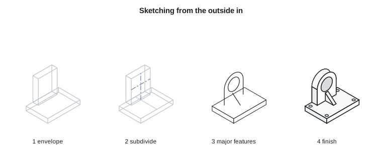
The basic method is to choose one dimension as a unit and estimate the others as multiples of it. Hold your pencil at arm's length, align its tip with one edge of the object, and slide your thumb to mark the length; then compare that length with other edges. Block in the overall envelope first, as a rectangle or box, then subdivide it: halves, thirds, quarters. Only then add holes, ribs and fillets. Working from the largest shapes to the smallest keeps the proportions right, because small errors in detail do not compound into large errors in the overall shape.
Sketching orthographic views
Orthographic views, the flat front, top and side views covered in lesson 3, are the most common engineering sketches. Sketch them on square grid paper, aligned so that the views share dimensions: the top view directly above or below the front view, sharing widths, and the side view beside it, sharing heights. Light projection lines between views keep features aligned. Begin each view with its envelope rectangle, sized from the overall dimensions, and add features in all views together rather than finishing one view at a time; this exposes inconsistencies early.
When sketching an existing part to record its geometry, it pays to include more views than you think you need and to note measurements directly on the sketch. Owen's field sketch of the old bracket showed a front view, a side view and a top view, with the bolt spacing, the bore centre height and the guard clearance written on them. Farah later added a partial section through the rib, because the rib's thickness could not be seen in any of the three views.
Pictorial sketches
Pictorial sketches show an object in three dimensions in a single view. They are easier for non-specialists to understand and invaluable for explaining a design. The isometric pictorial is the most common: its three principal axes are drawn 120 degrees apart, one vertical and two at 30 degrees to the horizontal, and lengths along all three axes are drawn at the same scale. Oblique pictorials draw the front face true shape and the depth receding at an angle, usually 45 degrees. Perspective sketches add vanishing points and look most natural but distort measurements. Lesson 4 covers the theory of these projections; here the focus is on sketching them quickly.
To sketch an isometric box, draw a vertical line for the nearest corner, then two lines at 30 degrees up to the left and right from its base, and complete the box with lines parallel to these three directions. Every edge of a rectangular object that is parallel to one of the principal axes is drawn parallel to one of these three directions. Edges that are not parallel to an axis, called non-isometric lines, cannot be measured directly; find their end points along isometric lines and join them.
Circles on the faces of an isometric box appear as ellipses. Sketch them by first drawing the isometric square that encloses the circle, a rhombus, and marking the midpoints of its sides. The ellipse touches those four midpoints and is tangent to the sides there. Its long axis lies along the long diagonal of the rhombus. A common error is to draw the ellipse tilted the wrong way: the minor axis of an isometric ellipse always lines up with the axis of the hole, perpendicular to the face.
Worked problem
Laying out an isometric sketch
Owen wants to sketch the bracket's envelope in isometric. The base plate is 120 mm long (x), 80 mm deep (y) and 15 mm thick; the upright wall is 70 mm wide, 20 mm thick and stands 85 mm above the base along the back edge, centred on the length. On isometric paper, x runs down to the right at 30°, y down to the left at 30°, and z vertically. Where does the far upper right corner of the base plate land, relative to the near lower corner, at full size?
Show solution
- The far upper right corner is at \((x, y, z) = (120, 80, 15)\) mm.
- The horizontal position on the paper is \(u = (x - y)\cos 30^\circ = (120 - 80)(0.866) = 34.6\) mm to the right.
- The vertical position is \(v = z - (x + y)\sin 30^\circ = 15 - (200)(0.5) = -85\) mm, that is, 85 mm below the starting corner on this layout.
- Repeating for all corners of both blocks, the whole envelope spans about 173 mm by 158 mm on the paper.
Answer: The corner lands 34.6 mm right and 85 mm down. In practice no one computes this when sketching; the point is that every isometric length is measured along the 30° directions at true scale, so the sketch can be laid out by counting grid squares.
The program below does the bookkeeping for the whole envelope, converting each corner of the base and upright into paper coordinates, finding the extent of the sketch, and checking the proportions the sketch must preserve.
import math

# Isometric sketch coordinates: the x axis runs down-right at 30 degrees,
# the y axis down-left at 30 degrees (depth), and z straight up.
c30, s30 = math.cos(math.radians(30)), math.sin(math.radians(30))

def iso(x, y, z):
    u = (x - y) * c30          # horizontal position on the paper
    v = z - (x + y) * s30      # vertical position on the paper
    return round(u, 1), round(v, 1)

# Bounding boxes of the BB-210 bracket, in mm: base plate and upright.
base = (120, 80, 15)            # length x, depth y, height z
upright = (70, 20, 85)          # upright wall, in the middle of the length, along the back edge

def box_corners(dx, dy, dz, x0=0, y0=0, z0=0):
    return [(x0 + i * dx, y0 + j * dy, z0 + k * dz) for k in (0, 1) for j in (0, 1) for i in (0, 1)]

print("Base plate corners -> paper coordinates (mm, full size):")
for p in box_corners(*base):
    print(f"  {p} -> {iso(*p)}")

pts = box_corners(*base) + box_corners(*upright, x0=25, y0=60, z0=15)
us = [iso(*p)[0] for p in pts]; vs = [iso(*p)[1] for p in pts]
w, h = max(us) - min(us), max(vs) - min(vs)
print(f"\nSketch extent at full size: {w:.0f} mm wide x {h:.0f} mm tall")

# How big will the sketch be on a grid with 5 mm squares if one square = 10 mm of part?
squares_per_mm = 1 / 10
print(f"On a 5 mm grid at 1 square = 10 mm: {w*squares_per_mm:.1f} x {h*squares_per_mm:.1f} squares")

# Proportion check: ratios a sketch must preserve even when no dimensions are known.
L, D, H = 120, 80, 15 + 85
print(f"\nProportions to keep: length/depth = {L/D:.2f}, total height/length = {H/L:.2f}")Base plate corners -> paper coordinates (mm, full size): (0, 0, 0) -> (0.0, 0.0) (120, 0, 0) -> (103.9, -60.0) (0, 80, 0) -> (-69.3, -40.0) (120, 80, 0) -> (34.6, -100.0) (0, 0, 15) -> (0.0, 15.0) (120, 0, 15) -> (103.9, -45.0) (0, 80, 15) -> (-69.3, -25.0) (120, 80, 15) -> (34.6, -85.0) Sketch extent at full size: 173 mm wide x 158 mm tall On a 5 mm grid at 1 square = 10 mm: 17.3 x 15.8 squares Proportions to keep: length/depth = 1.50, total height/length = 0.83
Visualization: reading shape from views
Sketching and visualization reinforce each other. Visualization is the ability to form an accurate mental image of an object from its views, and to imagine it rotated, cut or combined with other shapes. People differ in how easily they visualize, but the skill improves quickly with practice, and sketching is the best practice there is. Research on spatial training for engineering students has repeatedly found that short courses in sketching and visualization raise test scores and help retention in early engineering courses.
Several habits help. Identify surfaces, not just lines: each closed area in a view is a surface, and a surface that is flat and perpendicular to the line of sight appears in its true shape, while an inclined surface appears foreshortened in two views and as a line in the third. Number the corners of a surface in one view and find the same corners in the others. Look for similar shapes: an L-shaped surface in one view appears as an L-shaped surface, or as a line, in every other view. When stuck, sketch a pictorial: building the object in isometric from its views forces each feature to be placed consistently.
Another useful exercise is to model with simple materials. Engineers have long used modelling clay, foam or a block of soap to cut shapes from their views; a few minutes of carving often clarifies an intersection that is hard to imagine. Today a quick 3D model serves the same purpose, but the mental skill still matters, because you must recognize when the model you built does not match the intent.
Annotating and recording field sketches
A sketch used to record an existing part, or a condition in the field, becomes a record. It should carry the date, the location, the name of the person who made it, the units, and the method of measurement for critical values. Distinguish measured values from estimates: one convention is to write estimates with a tilde or in brackets. Measure from functional references, such as a machined face or the axis of a bore, rather than from rough cast surfaces. And photograph the object with a scale or a tape measure in the frame, so that the sketch can be checked later.
Sketching in design reviews
In design reviews, a sketch on a whiteboard or a markup on a print is often more effective than a model. It invites others to change it. Engineers routinely sketch over prints in red to show proposed changes, and those markups go into the change process described in lesson 12. When Farah's team reviewed the new BB-210 concept, Owen's sketch of the guard interference led to a decision to lower the bore centre by 5 mm and to add a rib on the front face, both of which were decided in ten minutes with a marker.
Common mistakes
MistakeStarting with details and working outward.
InsteadBlock in the overall envelope first, then subdivide; details placed on a correct envelope stay in proportion.
MistakeDrawing all lines with the same weight.
InsteadKeep construction lines light, visible outlines dark, and hidden and centre lines thin and patterned.
MistakeSketching isometric ellipses tilted the wrong way.
InsteadThe minor axis of an isometric ellipse is parallel to the axis of the hole.
MistakeMeasuring features from rough cast surfaces.
InsteadMeasure from functional references such as machined faces and bore axes.
MistakeLeaving field sketches undated and unsigned.
InsteadA field sketch is a record: date it, sign it, state the units and note how values were measured.
Summary and key terms
- Freehand sketching is fast, flexible and dominant in the early stages of design and in field work.
- Straight lines come from arm movement and light construction lines; circles are built from enclosing squares or radial marks.
- Proportion matters more than scale: block in the envelope, subdivide, then add detail.
- Orthographic sketches align views so that they share dimensions; features are added to all views together.
- Isometric sketches use three axes 120° apart with true lengths along each; circles become ellipses whose minor axis lies along the hole axis.
- Visualization improves with practice; reading surfaces and corners across views is the core skill.
- Field sketches are records and must carry date, author, units and measurement notes.
- Freehand sketch
- A drawing made without instruments to explore, explain or record a shape.
- Construction line
- A light line used to lay out a sketch, later left faint or erased.
- Proportion
- The relative sizes of the parts of an object, kept correct in a sketch even when it is not to scale.
- Isometric sketch
- A pictorial sketch with three principal axes 120° apart and equal scales along each.
- Non-isometric line
- An edge not parallel to an isometric axis, located by its end points.
- Visualization
- The ability to form and manipulate a mental image of a three-dimensional object.
- Markup
- A sketch or note drawn over an existing drawing to show a proposed change.
Practice problems
Work each problem on paper first, then reveal the answer to check.
Describe the box method for sketching a small circle.
Show answer
Sketch a light square, mark midpoints of its sides, and draw four arcs tangent to the sides at those midpoints.
Why should an isometric ellipse's minor axis line up with the hole axis?
Show answer
Because the circle lies in a plane perpendicular to that axis, and projection shortens the circle most along the direction of the axis.
A part is 90 mm long and 30 mm deep. If your sketch shows the length as 12 squares, how many squares should the depth be?
Show answer
4 squares, keeping the ratio of 3.
Using the formulas in the example, where does the point (0, 80, 0) land on the paper?
Show answer
u = −69.3 mm, v = −40 mm: 69.3 mm to the left and 40 mm down.
Why should a field sketch distinguish measured values from estimates?
Show answer
So that later users know which values can be trusted for design and which need checking.
Change the program so the upright is 100 mm tall. How does the sketch height change?
Show answer
It grows by 15 mm, to about 173 mm.
Lesson quiz · 5 questions
Score 60% or more to complete this lesson.
Create a free account to save your progress, take quizzes and earn a certificate.