
MEC-260 · Lesson 12 of 12 · 25 min
Parametric modelling, assemblies and drawing release
The last month of Owen's work term brought the BB-210 together. The bracket existed as a parametric 3D model, placed in an assembly with the bearing, cover, grease fitting and screws, and that assembly sat inside the full pump model. From the bracket model came the casting drawing, the machining drawing and the inspection plan; from the assembly came the exploded view and bill of materials in the service manual. Then a customer asked for a version with a larger bearing. Owen changed one parameter, the bore diameter, watched the model rebuild, checked the wall thickness, and had a new drawing ready for review in an afternoon. The rest of this lesson explains how that kind of model is built, and how it moves from an engineer's screen to a released, controlled design.
Parametric, feature-based modelling
Most mechanical design today uses parametric, feature-based solid modelling. A part is built as a sequence of features, such as extrusions, revolves, holes, fillets, chamfers, shells and patterns, each driven by dimensions and constraints that the designer can change later. The sequence is recorded in a feature tree, or history, and changing an early feature updates everything that depends on it. The model is a solid: it knows its volume, mass, centre of gravity and inertia, and it can be sectioned, measured and analyzed. Direct, or history-free, modelling, which lets the designer push and pull faces without a feature history, complements parametric modelling and is common for editing imported geometry and for early concept work. Many programs offer both.
Most features start from a 2D sketch on a plane or a face. The sketch is made of lines, arcs and circles, and its shape is fixed by two kinds of constraints. Geometric constraints, such as horizontal, vertical, parallel, perpendicular, tangent, concentric, equal and coincident, fix relationships. Dimensional constraints fix sizes and distances. A sketch with every degree of freedom removed is fully constrained, and good practice is to fully constrain every sketch, so that it cannot change shape unexpectedly when something else is edited.
Design intent
The most important idea in parametric modelling is design intent: building the model so that it changes the way the design should change. Two models can look identical and behave very differently when edited. If the bracket's bore is dimensioned 65 mm from the mounting face, changing the base thickness leaves the bore where the shaft needs it. If the bore were dimensioned 50 mm from the top of the base, the same edit would move the shaft. The first model captures the intent that the shaft height is fixed by the pump; the second does not.
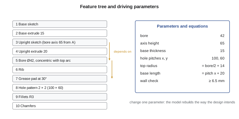
Capturing intent means choosing references and dimensions the same way as on a drawing: from functional features. It also means using relations and equations where the design has rules. On the BB-210, the rounded top of the upright is concentric with the bore and its radius equals the bore radius plus 14 mm, so a larger bearing automatically gives a larger top. The base length equals the hole pitch plus 20 mm, so the holes stay 10 mm from the ends. The mounting holes are a pattern driven by two pitches. Owen's one-parameter change for the larger bearing worked because these rules were built in.
Worked problem
Testing design intent
The bracket model is driven by bore = 42 mm, centre height = 65 mm above the mounting face and base thickness = 15 mm, with the top radius equal to bore/2 + 14 mm. The company requires at least 6.5 mm of cast wall between the bore and any outer surface. Check the released design, a version with a 47 mm bore, and a proposal to lower the shaft to 42 mm.
Show solution
- Released design: top radius \(21 + 14 = 35\) mm, top of upright at \(65 + 35 = 100\) mm. Wall below the bore \(= 65 - 21 - 15 = 29\) mm; wall at the top \(= 14\) mm. Both exceed 6.5 mm.
- 47 mm bore: top radius \(23.5 + 14 = 37.5\) mm, top at 102.5 mm; wall below the bore \(= 65 - 23.5 - 15 = 26.5\) mm. Acceptable, and the top grows automatically.
- Shaft at 42 mm: wall below the bore \(= 42 - 21 - 15 = 6.0\) mm, below the 6.5 mm minimum.
Answer: The first two variants rebuild correctly. The third breaks a design rule, which a well-built model can flag automatically with a check on the computed wall. Lowering the shaft would require a thinner base or a different casting, a decision for the engineer, not the software.
The program expresses the same model as equations and checks the wall rule for each variant, then rolls up an indented bill of materials for the bearing assembly.
# Part 1: design intent as equations. Driving parameters set the bracket; the others follow.
def bracket(bore=42.0, axis_height=65.0, base_t=15.0, wall=6.5, hole_pitch_x=100.0, hole_pitch_y=60.0):
    p = {'bore': bore, 'axis_height': axis_height, 'base_t': base_t}
    p['top_radius'] = bore / 2 + 14                 # rounded top of the upright, concentric with the bore
    p['upright_top'] = axis_height + p['top_radius']
    p['wall_below_bore'] = axis_height - bore / 2 - base_t
    p['base_length'] = hole_pitch_x + 20            # 10 mm from each hole axis to the end
    p['base_depth'] = hole_pitch_y + 20
    p['ok'] = p['wall_below_bore'] >= wall and p['top_radius'] - bore / 2 >= wall
    return p

for label, kw in (('released design', {}), ('bigger bearing, 47 mm', {'bore': 47.0}),
                  ('lower shaft, 42 mm', {'axis_height': 42.0})):
    p = bracket(**kw)
    print(f"{label:22s} top R{p['top_radius']:.1f}, height {p['upright_top']:.1f}, "
          f"wall below bore {p['wall_below_bore']:.1f} mm -> {'meets' if p['ok'] else 'violates'} the 6.5 mm minimum wall")

# Part 2: an indented bill of materials for the outboard bearing assembly, rolled up.
bom = [
    (0, 'PA-400', 'Outboard bearing assembly', 1, None),
    (1, 'BB-210', 'Bracket, bearing (cast, machined)', 1, 0.62),
    (1, 'BRG-6004', 'Ball bearing 6004-2RS', 1, 0.07),
    (1, 'CV-115', 'Cover, bearing', 1, 0.09),
    (2, 'SC-M5x12', 'Screw, socket head M5 x 12, class 8.8', 2, 0.004),
    (1, 'GF-M6', 'Grease fitting M6 x 1', 1, 0.01),
    (1, 'SC-M8x30', 'Screw, hex head M8 x 30, class 8.8', 4, 0.016),
    (1, 'WA-M8', 'Washer, plain M8', 4, 0.003),
]
print("\nIndented BOM (qty per parent):")
mult = {0: 1}; mass = 0.0; totals = {}
for level, pn, desc, qty, m in bom:
    mult[level] = mult.get(level - 1, 1) * qty if level else qty
    total_qty = mult[level]
    if m is not None:
        mass += total_qty * m
        totals[pn] = totals.get(pn, 0) + total_qty
    print(f"  {'  ' * level}{pn:10s} {desc:42s} {qty}")
print("\nRolled-up quantities per assembly:", totals)
print(f"Assembly mass about {mass:.3f} kg")released design top R35.0, height 100.0, wall below bore 29.0 mm -> meets the 6.5 mm minimum wall
bigger bearing, 47 mm top R37.5, height 102.5, wall below bore 26.5 mm -> meets the 6.5 mm minimum wall
lower shaft, 42 mm top R35.0, height 77.0, wall below bore 6.0 mm -> violates the 6.5 mm minimum wall
Indented BOM (qty per parent):
PA-400 Outboard bearing assembly 1
BB-210 Bracket, bearing (cast, machined) 1
BRG-6004 Ball bearing 6004-2RS 1
CV-115 Cover, bearing 1
SC-M5x12 Screw, socket head M5 x 12, class 8.8 2
GF-M6 Grease fitting M6 x 1 1
SC-M8x30 Screw, hex head M8 x 30, class 8.8 4
WA-M8 Washer, plain M8 4
Rolled-up quantities per assembly: {'BB-210': 1, 'BRG-6004': 1, 'CV-115': 1, 'SC-M5x12': 2, 'GF-M6': 1, 'SC-M8x30': 4, 'WA-M8': 4}
Assembly mass about 0.874 kgGood modelling practice
Experienced designers follow a few habits that keep models robust. Build the major shape first and add small features such as fillets and chamfers last, because fillets are the features most likely to fail when geometry changes. Reference stable geometry, such as datum planes, the origin and functional faces, rather than edges that may disappear. Mirror and pattern features rather than modelling copies. Name important features and parameters so others can find them. Keep sketches simple. And build the model to reflect manufacturing where it helps: a casting model with draft and fillets, and a machining model derived from it, mirrors the two drawings the shop needs.
Models are also tested, just as code is. Change the key parameters through their expected range and confirm the model rebuilds without errors and keeps the intended relationships. Check mass properties against an estimate. Section the part to look at wall thickness. A model that only works at one set of values is fragile and will cost someone time later.
Assemblies
An assembly model places parts and subassemblies relative to each other using mates, also called constraints or joints: coincident faces, concentric axes, distances and angles. Mates should reflect real assembly: the bracket's mounting face is coincident with the pump base pad, its back face against the shoulder, its holes concentric with the tapped holes. Mated correctly, an assembly can be used to check interference, measure clearances, simulate motion and calculate the mass and centre of gravity of the whole product. Owen's first assembly check found that the grease fitting touched the coupling guard by 1.5 mm, which led to the 30° tilt of the pad.
Large products are built as structured assemblies: the pump contains a bearing assembly, which contains the bracket, the bearing and the cover. The structure should match how the product is built and serviced, because it becomes the structure of the bill of materials. Top-down design, in which part geometry is derived from a layout or skeleton in the assembly, helps keep related parts consistent, while bottom-up design builds parts independently and assembles them; most projects mix the two.
Assembly drawings and bills of materials
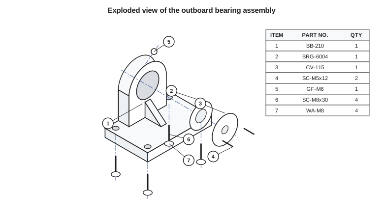
An assembly drawing shows how parts go together and identifies them. It typically includes one or more views, often a section or an exploded pictorial, balloons that number each part, and a parts list or bill of materials (BOM) giving item number, part number, description, material and quantity. It carries only assembly-level information: overall dimensions, required clearances, tightening torques, adhesives and lubrication. Detail dimensions belong on the detail drawings.
The BOM is one of the most important documents a company produces, because it drives purchasing, production planning, costing and service parts. An engineering BOM reflects the design structure; a manufacturing BOM may reorganize it to reflect how the product is built, adding items such as grease, packaging and labels. An indented BOM shows the hierarchy, and a rolled-up or summarized BOM totals each part across the hierarchy. Modelling programs generate BOMs from the assembly automatically, which is a strong reason to model standard parts with correct designations, as lesson 11 recommended.
Revision control and engineering changes
A released drawing or model is a controlled document. Changes go through an engineering change process: an engineering change request (ECR) describes the problem or proposal; a review decides whether to proceed and evaluates the effect on stock, tooling, suppliers, service and certification; an engineering change order or notice (ECO or ECN) authorizes the change; the drawing's revision letter advances, and the revision block records what changed, why, when and by whom. ASME Y14.35 describes revision practices. A change that affects interchangeability, so that new parts cannot replace old ones or the reverse, usually requires a new part number rather than just a new revision, because people in the field order by part number.
For the BB-210, the new grease pad changed the part's form but not its fit with the pump, so the bracket kept its part number and advanced from revision C to revision D. The larger-bearing version could not replace the original, so it became a new part, BB-212, with its own drawing derived from the same model family. Product lifecycle management (PLM) and product data management (PDM) systems hold the models, drawings and BOMs, control who can change them, record approvals and keep every revision retrievable. When a field technician orders a replacement bracket in fifteen years, the PLM record links the serial number of the pump to the exact revision that was installed.
Model-based definition and the digital thread
Model-based definition, introduced in lesson 1, places dimensions, tolerances, datums and notes directly on the 3D model as product and manufacturing information (PMI), following ASME Y14.41 and ISO 16792. The annotated model then becomes the authority for manufacturing and inspection. Machine shops program from it, inspection software reads the tolerances to create measurement plans automatically, and suppliers receive one file instead of a model and a drawing that might disagree. The chain of data from design through manufacture, inspection and service is often called the digital thread.
MBD does not remove the need for the skills in this course; it changes where they are applied. Datums, feature control frames, sections and views still exist, now as annotations and saved views in the model. A company moving to MBD needs designers who understand GD&T well enough to annotate a model completely, because there is no drawing review where a missing tolerance might be spotted. Neutral formats such as STEP AP242 carry the geometry and the PMI between systems, and lightweight viewers let people without modelling software read the annotations.
Capstone: the BB-210 release package
Owen's final task was to assemble the release package for the revised bracket and present it at the design review. It contained the casting drawing, showing the raw casting with draft, fillets and machining allowances and a profile tolerance to the model; the machining drawing, with the datum scheme A, B and C, the 42 H7 bore with its cylindricity, parallelism and position tolerances, the mounting holes with position at MMC, the grease pad in a partial auxiliary view with its angularity and tapped hole, and section A–A through the bore; the assembly drawing with the exploded view, balloons, BOM and tightening torques; the updated model with its parameters, equations and design checks; an ECO describing the change from revision C to D; and Marco's inspection plan, derived from the drawing's datums and tolerances.
The review took forty minutes. The machine shop supervisor asked one question, about the edge break on the bore, and Marco said the inspection plan was the first one he had not had to rewrite. Farah signed the release. Every element of the package used something from this course: projection, sections, auxiliary views, dimensioning, fits, GD&T, thread callouts, modelling and revision control. Taken together, they let a part designed in one office be cast in one province or state, machined in another, inspected in a third and assembled into pumps that ship around the world, with nobody needing to ask what the designer meant.
Common mistakes
MistakeDimensioning sketch features from whatever edge is nearest.
InsteadReference functional features and datum planes so the model changes the way the design should.
MistakeLeaving sketches under-constrained.
InsteadFully constrain every sketch so that edits elsewhere cannot change its shape unexpectedly.
MistakeAdding fillets early in the feature tree.
InsteadAdd fillets and chamfers late; they are the features most likely to fail on change.
MistakeChanging a part's fit or interchangeability without a new part number.
InsteadNon-interchangeable changes need new part numbers; compatible changes advance the revision.
MistakeAssuming MBD removes the need for GD&T skills.
InsteadMBD needs complete, correct annotation of the model, which requires the same skills.
Summary and key terms
- Parametric, feature-based models are driven by dimensions, constraints and a feature history; direct modelling complements them.
- Design intent means building models so they change the way the design should, by referencing functional features and using equations.
- Robust models fully constrain sketches, reference stable geometry, add fillets late and are tested across parameter ranges.
- Assemblies use mates that reflect real assembly and support interference checks, motion and mass properties.
- Assembly drawings carry balloons, a bill of materials and assembly-level information; BOMs drive purchasing and production.
- Released designs change through ECRs and ECOs; revisions record compatible changes, new part numbers mark non-interchangeable ones.
- Model-based definition puts PMI on the model as the authority, but relies on the same graphics and GD&T skills.
- Feature tree
- The ordered list of features that builds a parametric model.
- Fully constrained sketch
- A sketch with all degrees of freedom removed by geometric and dimensional constraints.
- Design intent
- The way a model is built so that it responds to changes as the design requires.
- Mate
- A constraint that positions a part relative to another in an assembly.
- Bill of materials
- A structured list of the parts and quantities in an assembly.
- Engineering change order
- The authorization that releases a change to a controlled design.
- Product lifecycle management
- Systems and processes that manage product data, revisions and approvals over a product’s life.
- Product and manufacturing information
- Dimensions, tolerances, datums and notes attached to a 3D model.
Practice problems
Work each problem on paper first, then reveal the answer to check.
Why should the bore be dimensioned from the mounting face in the sketch rather than from the top of the base?
Show answer
The shaft height is set by the pump relative to the mounting face; this reference keeps it fixed when the base thickness changes.
What is the difference between an indented and a rolled-up BOM?
Show answer
An indented BOM shows the hierarchy; a rolled-up BOM totals each part across all levels.
A change makes new brackets unable to replace old ones. Should the revision letter change or the part number?
Show answer
The part number, because the parts are no longer interchangeable.
Name three uses of a correctly mated assembly model.
Show answer
Any three of: interference checks, clearance measurement, motion simulation, mass properties, BOM generation.
What does STEP AP242 carry that older neutral formats did not?
Show answer
Product and manufacturing information (PMI) along with the geometry.
In the program, what is the lowest centre height that still meets the 6.5 mm wall rule with a 42 mm bore?
Show answer
Bore radius plus base thickness plus wall: 21 + 15 + 6.5 = 42.5 mm.
Lesson quiz · 5 questions
Score 60% or more to complete this lesson.
Create a free account to save your progress, take quizzes and earn a certificate.