
LVT-310 · Lesson 4 of 12 · 22 min
Amplifiers and loudspeakers: 70 V and low-impedance systems
Riverside's paging system has 210 ceiling speakers and 38 corridor and wall speakers, spread over three floors and a gym, driven from four racks. Brightwater's boardroom has six ceiling speakers on a single amplifier channel a few metres away. The two jobs use different ways of connecting loudspeakers to amplifiers, and an installer who mixes them up can destroy an amplifier in seconds or leave a system so quiet nobody can hear it. This lesson covers what an amplifier does and how it is rated, loudspeaker impedance and low-impedance wiring, constant-voltage distributed systems at 70 V and 100 V, transformer taps and amplifier sizing, speaker cable losses, loudspeaker types and coverage, and the checks an installer makes before connecting an amplifier.
What an amplifier does
A power amplifier takes a line-level signal of about a volt and makes a copy large enough to move loudspeaker cones: tens of volts and several amperes. Its rating states how much power it can deliver continuously into a stated load without exceeding a stated distortion, for example 250 W per channel into 4 ohms, or 250 W into a 70 V line. Modern installed amplifiers are mostly class D designs, which switch their output transistors on and off very quickly and filter the result, wasting little power as heat. That matters in a rack: an amplifier that is 85 to 90 per cent efficient at full power produces far less heat than an older design, and lesson 11 uses the heat figures to size rack cooling.
An amplifier can be damaged by the wrong load. Connected to a load whose impedance is lower than its rating, it tries to deliver more current than it was built for, overheats and shuts down or fails; a short circuit on a speaker line is the extreme case. Most installed amplifiers protect themselves by limiting or muting, but the fault still has to be found. Connecting the wrong kind of load, such as low-impedance speakers on an amplifier output set for 70 V, can also damage the speakers.
Loudspeaker impedance and low-impedance wiring
A loudspeaker's impedance is its opposition to the amplifier's alternating current, given as a nominal figure in ohms, usually 4, 8 or 16 ohms. Impedance varies with frequency, but the nominal figure is what the installer uses for wiring. In a low-impedance system, the speakers connect directly to the amplifier, in series, in parallel, or in combinations, and the total impedance seen by the amplifier must not fall below its minimum rating. Two 8-ohm speakers in parallel present 4 ohms; in series, 16 ohms. Four 8-ohm speakers in series-parallel, two series pairs in parallel, present 8 ohms.
Low-impedance wiring suits small systems with short cable runs: a boardroom, a classroom with a few speakers on a local amplifier, a music system. Its advantages are simple wiring and good sound with no transformers. Its limits are that only a few speakers fit on each channel, every speaker gets the same power, and long runs waste power in the cable, because the current is high. Polarity matters: every speaker's plus terminal should connect to the amplifier's plus, so the cones move together; one reversed speaker partly cancels its neighbours, especially at low frequencies.
# Impedance of low-impedance speaker combinations
def series(*z): return sum(z)
def parallel(*z): return 1 / sum(1 / x for x in z)
print(f"Two 8-ohm speakers in parallel:          {parallel(8, 8):.1f} ohms")
print(f"Four 8-ohm speakers in parallel:         {parallel(8, 8, 8, 8):.1f} ohms  (too low for a 4-ohm amp)")
print(f"Two series pairs of 8-ohm, in parallel:  {parallel(series(8, 8), series(8, 8)):.1f} ohms")
print(f"Six 8-ohm speakers, three series pairs:  {parallel(series(8, 8), series(8, 8), series(8, 8)):.2f} ohms")
amp_min = 4.0
for n in range(1, 7):
    z = parallel(*([8.0] * n))
print(f" {n} x 8 ohm in parallel = {z:4.2f} ohms -> {'ok' if z >= amp_min else 'below amplifier minimum'}")Two 8-ohm speakers in parallel: 4.0 ohms Four 8-ohm speakers in parallel: 2.0 ohms (too low for a 4-ohm amp) Two series pairs of 8-ohm, in parallel: 8.0 ohms Six 8-ohm speakers, three series pairs: 5.33 ohms 1 x 8 ohm in parallel = 8.00 ohms -> ok 2 x 8 ohm in parallel = 4.00 ohms -> ok 3 x 8 ohm in parallel = 2.67 ohms -> below amplifier minimum 4 x 8 ohm in parallel = 2.00 ohms -> below amplifier minimum 5 x 8 ohm in parallel = 1.60 ohms -> below amplifier minimum 6 x 8 ohm in parallel = 1.33 ohms -> below amplifier minimum
Brightwater's six boardroom speakers are wired as three series pairs in parallel, giving about 5.3 ohms on one channel of an amplifier rated down to 4 ohms. Wiring all six in parallel would have given 1.3 ohms, which the amplifier would refuse.
Constant-voltage distributed systems
Large paging systems use constant-voltage distribution, almost always called a 70-volt system in Canada and the United States, or 100-volt in much of the rest of the world. The amplifier's output is designed to swing to a maximum of 70.7 volts at full rated power, regardless of how many speakers are connected, up to its power rating. Each loudspeaker has a small step-down transformer with taps, such as 0.5, 1, 2, 4 and 8 watts, and the installer chooses the tap that sets how much power that speaker draws at full output. Dozens of speakers connect in parallel across one pair of wires, each taking its tapped power, and the amplifier only needs to be rated for the total of the taps plus headroom.
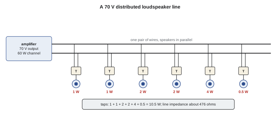
The higher voltage means lower current for the same power, so cable losses are smaller and long runs with modest wire are practical. Each speaker's level can be set individually by its tap, so a speaker near a noisy machine can be tapped up and one in a quiet office tapped down. Adding a speaker is just another parallel connection, as long as the amplifier has capacity. The cost is a transformer in every speaker, which slightly limits low-frequency response and adds a small loss, which is why 70 V suits speech and background music rather than high-fidelity sound. In Canada and the United States, 70 V speaker circuits are normally Class 2 or Class 3 circuits under the electrical code, wired with suitably rated cable; LVT-330 covers the rules.
Some systems use 25 V lines for small installations where a lower voltage avoids certain wiring requirements, and some large venues use 100 V or higher. Whatever the voltage, the principle is the same: the amplifier's rated output voltage is the line voltage, and the speaker taps must match that voltage. A speaker with 70 V taps connected to a 100 V line draws twice the tapped power; one with 100 V taps on a 70 V line draws half.
Sizing the amplifier
For a 70 V zone, the installer or designer adds up the taps of every speaker on the line and chooses an amplifier channel rated for that total plus about 20 to 25 per cent headroom. The headroom covers transformer losses, line losses and the peaks of speech and music, and allows a few speakers to be added later. An amplifier loaded to more than its rated power clips on loud pages and may shut down; one loaded far below its rating works but wastes capacity.
# Riverside floor 2 paging zones: sum taps, size amplifier channels with headroom
zones = {  # zone: list of (quantity, tap watts)
    "2 north classrooms": [(28, 1.0)],
    "2 south classrooms": [(30, 1.0)],
    "2 corridors":        [(16, 2.0), (6, 4.0)],
    "2 washrooms/stairs": [(10, 0.5)],
    "library":            [(12, 0.5)],
}
HEADROOM = 1.25
CHANNEL_SIZES = [60, 120, 250, 500]
for z, spk in zones.items():
    total = sum(q * t for q, t in spk)
    need = total * HEADROOM
    pick = next(c for c in CHANNEL_SIZES if c >= need)
    n = sum(q for q, _ in spk)
print(f"{z:20s} {n:3d} speakers, taps {total:6.1f} W, need {need:6.1f} W -> {pick} W channel")2 north classrooms 28 speakers, taps 28.0 W, need 35.0 W -> 60 W channel 2 south classrooms 30 speakers, taps 30.0 W, need 37.5 W -> 60 W channel 2 corridors 22 speakers, taps 56.0 W, need 70.0 W -> 120 W channel 2 washrooms/stairs 10 speakers, taps 5.0 W, need 6.2 W -> 60 W channel library 12 speakers, taps 6.0 W, need 7.5 W -> 60 W channel
The floor 2 corridor zone, with its louder taps, needs a 120 W channel; the quiet library zone needs only 7.5 W and shares a small channel. Grouping speakers into zones is also how the paging system lets the office page one area, which lesson 5 covers.
Speaker cable losses
Speaker cable has resistance, and the current flowing through it loses voltage and power before it reaches the speakers. For a 70 V line, the load impedance of the whole line is the line voltage squared divided by the total tapped power: a 100 W line has a load of about 50 ohms. The cable's loop resistance, both conductors, forms a voltage divider with that load. A common design limit is a loss of no more than about 0.5 to 1 dB at the farthest speaker, which is about 10 to 20 per cent of the power. Low-impedance runs are far more sensitive: an 8-ohm speaker on a long thin cable can lose a large share of its power, which is why low-impedance runs are kept short or use heavy wire.
# Voltage and power loss on a 70 V line and on a low-impedance run
import math
OHM_PER = {18: 0.021, 16: 0.0132, 14: 0.0083, 12: 0.0052}   # ohms per metre of one conductor
def loss_db(z_load, length, awg):
    r_loop = 2 * length * OHM_PER[awg]
    return 20 * math.log10((z_load + r_loop) / z_load), r_loop
print("70 V line, 100 W of taps:")
z70 = 70.7 ** 2 / 100
for awg in (18, 16, 14):
    db, r = loss_db(z70, 150, awg)
    print(f"  {awg} AWG, 150 m: loop {r:4.2f} ohms on a {z70:.0f}-ohm line -> loss {db:4.2f} dB")
print("Low-impedance, one 8-ohm speaker:")
for awg in (18, 16, 14, 12):
    db, r = loss_db(8.0, 30, awg)
print(f" {awg} AWG, 30 m: loop {r:4.2f} ohms -> loss {db:4.2f} dB")70 V line, 100 W of taps: 18 AWG, 150 m: loop 6.30 ohms on a 50-ohm line -> loss 1.03 dB 16 AWG, 150 m: loop 3.96 ohms on a 50-ohm line -> loss 0.66 dB 14 AWG, 150 m: loop 2.49 ohms on a 50-ohm line -> loss 0.42 dB Low-impedance, one 8-ohm speaker: 18 AWG, 30 m: loop 1.26 ohms -> loss 1.27 dB 16 AWG, 30 m: loop 0.79 ohms -> loss 0.82 dB 14 AWG, 30 m: loop 0.50 ohms -> loss 0.52 dB 12 AWG, 30 m: loop 0.31 ohms -> loss 0.33 dB
A long 70 V corridor run on 16 AWG cable loses well under a decibel, while the same gauge on a much shorter run to a single 8-ohm speaker loses nearly as much. The design states the gauge for each run; the installer checks the actual route length, because a cable that wanders around a stairwell can be much longer than the plan suggests.
Loudspeaker types and coverage
Installed loudspeakers come in a few families. Ceiling speakers, round units in a back can that mount in a tile or drywall ceiling, are the workhorse of paging and background music; they fire downward with a coverage angle, often 90 to 120 degrees at the frequencies that matter for speech. Pendant speakers hang on cables from high or open ceilings. Surface-mount and wall speakers suit spaces without ceilings, such as stairwells and shops. Horn speakers concentrate sound into a narrow beam with high sensitivity, for warehouses, gyms and outdoors; reentrant horns are weatherproof. Column and line-array speakers are tall narrow cabinets that keep sound in a vertical beam, which helps in reverberant spaces like gyms by aiming sound at the listeners and away from walls and ceiling.
Each speaker's coverage angle is where its level has fallen 6 dB from the on-axis level, at a stated frequency. Lesson 5 uses that to space ceiling speakers. Coverage is narrower at high frequencies than low, so a speaker's useful coverage for speech intelligibility is the angle at about 2 to 4 kHz. Speakers must also be fire-rated where the ceiling or space requires it, with back cans, fire-rated enclosures or plenum-rated models as the code and the design call for.
Before connecting the amplifier
The most common way to damage an amplifier on a new job is to connect it to a speaker line with a short circuit, a nail through a cable, a staple, a strand across terminals in a back can. Before any 70 V line is connected, Cobalt Line checks it with an impedance meter, an instrument that measures the line's impedance at an audio frequency, usually 1 kHz. A healthy 70 V line with 100 W of taps reads about 50 ohms; one reading near zero has a short; one reading much higher than expected has an open or missing speakers; one reading too low has extra speakers or a wrong tap. A plain ohmmeter is not suitable for 70 V lines, because it measures the DC resistance of the transformer windings, not the audio impedance.
# Expected 70 V line impedance from the taps, compared with impedance meter readings
def expected(taps_w, volts=70.7):
    return volts ** 2 / taps_w
lines = [  # line, total taps W, reading ohms at 1 kHz
    ("2 north classrooms", 28.0, 172.0),
    ("2 corridors",        56.0,  91.0),
    ("2 south classrooms", 30.0,   0.6),
    ("library",             6.0, 410.0),
]
for name, taps, reading in lines:
    exp = expected(taps)
    ratio = reading / exp
    if reading < 2: verdict = "SHORT - do not connect"
    elif ratio > 1.3: verdict = "high - open or missing speakers"
    elif ratio < 0.75: verdict = "low - extra load or wrong taps"
    else: verdict = "ok"
print(f"{name:20s} taps {taps:5.1f} W expect {exp:6.1f} ohms, read {reading:6.1f} -> {verdict}")2 north classrooms taps 28.0 W expect 178.5 ohms, read 172.0 -> ok 2 corridors taps 56.0 W expect 89.3 ohms, read 91.0 -> ok 2 south classrooms taps 30.0 W expect 166.6 ohms, read 0.6 -> SHORT - do not connect library taps 6.0 W expect 833.1 ohms, read 410.0 -> low - extra load or wrong taps
The south classroom line reads a short: Maya traces it to a back can where the installer stapled the cable to a joist and the staple went through it. The library line reads low, about 410 ohms against an expected 833; it turns out to be correct, because the expected value used the design's 0.5 W taps and all twelve library speakers were tapped up to 1 W on site to suit the room, which doubles the load and halves the impedance. The change was recorded on the drawing, and the expected value is updated to match.
Worked problem
Why is the corridor so quiet?
At Riverside, the floor 3 corridor zone is much quieter than floor 2, though both use the same speakers and tap settings. The impedance meter shows the floor 3 line at about 104 ohms, twice the 52 ohms expected for its 96 W of taps. Its amplifier channel is a 250 W channel. Maya finds that floor 3's speakers are a different model from the drawing, with taps labelled for a 100 V line. What is happening and what should be done?
Show solution
- A transformer tapped for 2 W at 100 V draws only about half that, roughly 1 W, when driven at 70.7 V, because power goes with the square of voltage and (70.7/100) squared is 0.5.
- Each floor 3 speaker therefore runs about 3 dB quieter than intended.
- The fix is to move each speaker to the tap one step higher, which doubles its power back to the intended level at 70 V, or replace the speakers with the specified 70 V model.
- After retapping, the total load at 70 V matches the design's 96 W; the impedance meter now reads about 52 ohms, which confirms it.
Answer: Maya retaps the floor 3 speakers one step up after the designer approves the substitution, and the two corridors now measure within 1 dB of each other during a test page.
Common mistakes
MistakeConnecting a 70 V line without measuring its impedance.
InsteadCheck every line with an impedance meter at 1 kHz before connecting the amplifier.
MistakeWiring too many low-impedance speakers in parallel.
InsteadCalculate the total impedance and keep it above the amplifier's minimum.
MistakeSizing an amplifier to exactly the total of the taps.
InsteadAdd about 20 to 25 per cent headroom.
MistakeMixing 70 V and 100 V tapped speakers on one line.
InsteadUse taps rated for the line voltage, or retap and record the change.
MistakeReversing polarity on one speaker.
InsteadKeep plus to plus throughout, and check it.
Summary and key terms
- Amplifiers are rated for continuous power into a stated load; class D designs are efficient and run cool.
- Low-impedance systems wire speakers in series and parallel and must stay above the amplifier's minimum impedance.
- 70 V systems put many speakers in parallel, each with a transformer tap that sets its power.
- Size a 70 V amplifier channel at the total of the taps plus about 20 to 25 per cent.
- Line impedance is V squared over the tapped power; cable loss is kept to about 0.5 to 1 dB.
- Ceiling, pendant, wall, horn and column speakers suit different spaces; coverage angle is the −6 dB point.
- Measure every 70 V line with an impedance meter before connecting the amplifier.
- Impedance
- A loudspeaker’s opposition to alternating current, in ohms.
- 70 V system
- A constant-voltage speaker distribution system in which the amplifier delivers 70.7 V at full power.
- Transformer tap
- A connection on a speaker transformer that sets the power the speaker draws.
- Headroom
- Spare capacity above the expected load or level.
- Impedance meter
- An instrument that measures a speaker line’s impedance at an audio frequency.
- Coverage angle
- The angle at which a speaker’s level has fallen 6 dB from on-axis.
- Class D amplifier
- A switching amplifier design with high efficiency.
Practice problems
Work each problem on paper first, then reveal the answer to check.
What is the total impedance of two 8-ohm speakers in series?
Show answer
16 ohms.
A 70 V line carries 30 speakers tapped at 2 W. What channel size would you choose?
Show answer
At least 75 W with headroom, so a 120 W channel from a 60/120/250 range.
What impedance should a 70 V line with 50 W of taps read?
Show answer
About 100 ohms.
Why is a plain ohmmeter unsuitable for checking a 70 V line?
Show answer
It measures the DC resistance of the transformer windings, not the audio impedance.
Lesson quiz · 5 questions
Score 60% or more to complete this lesson.
Create a free account to save your progress, take quizzes and earn a certificate.