
HSE-323 · Lesson 9 of 12 · 28 min
Liquid cooling systems in AI-era data centres
For decades, data centres cooled servers with air and kept water at the edge of the room. Artificial intelligence changed that within a few years. Accelerator chips now dissipate around a kilowatt or more each, servers carry several of them, and racks built for training and running large models draw from about 40 kW to more than 100 kW, with the densest designs reported as of 2026 at about 120 to 140 kW and roadmaps for far more. Air can practically remove perhaps 20 to 30 kW from a rack. Above that, liquid has to carry the heat away from the chips, because water can hold roughly 3,500 times as much heat as the same volume of air.
This lesson describes the liquid cooling systems that workers now meet in data halls: rear-door heat exchangers, direct-to-chip cold plates with coolant distribution units, and immersion tanks. It explains how they are arranged, where the liquid is and at what temperatures and pressures, and who owns which part. Lesson 10 covers the hazards of the coolants and fluids themselves, and Lesson 11 covers leaks, spills and emergencies. The engineering of these systems, including heat rejection plants, pumps and piping, is covered in DCE-330, especially Lessons 6, 9 and 10.
Why liquid, and why now
The physics is simple. The heat a fluid can carry is the product of its mass flow, its specific heat capacity and its temperature rise: Q = ṁ × cp × ΔT. Water has a specific heat of about 4.18 kJ/(kg·K) and a density about 830 times that of air, so a modest flow of water carries the heat that would need an enormous flow of air. Moving heat in liquid also lets the coolant run warmer, which allows heat to be rejected outdoors with less chiller energy and, in some places, reused for district heating.
The market moved quickly. Industry surveys through 2025 and 2026 reported rapid growth in liquid cooling, led by direct-to-chip systems using water-based coolant, which by 2026 were widely described as the dominant approach for new AI deployments. Immersion cooling grew more slowly, and two-phase systems using fluorinated fluids were slowed by the PFAS phase-outs discussed in Lesson 10. For people on site, the result is that many data halls now contain a mixture of air-cooled racks, liquid-cooled racks and supporting equipment, often installed in stages while the hall is live, as at Cedar Ridge Hall 2.
Two loops: facility water and technology cooling
Most liquid cooling installations separate the liquid into two loops, using terms from ASHRAE guidance.
- The facility water system (FWS) is the building's cooling water: chilled water or warmer condenser or dry cooler water circulated by the central plant, often with glycol added to prevent freezing in outdoor equipment. It is large in volume, operated by the facility team and connected to chillers, dry coolers or cooling towers.
- The technology cooling system (TCS) is the smaller, cleaner loop that runs through the IT equipment: from a coolant distribution unit (CDU), through rack manifolds and hoses, through cold plates on the chips and back. It uses carefully controlled coolant, typically treated water or a water and propylene glycol mixture with corrosion inhibitors and sometimes a biocide.
- The coolant distribution unit links the two. Its heat exchanger transfers heat from the TCS to the FWS without mixing them, its pumps circulate the TCS, and it contains filters, an expansion tank, sensors, valves and controls. Some CDUs instead reject heat to the room air, as liquid-to-air units beside the rack.
Separating the loops lets the TCS use a clean, controlled coolant with a small volume, so that a leak in the IT space releases a limited amount of a known fluid. It also puts a clear boundary between building systems and IT systems, which matters for responsibility. In colocation sites, the FWS and often the CDU belong to the operator, and the rack manifolds, hoses and servers belong to the customer, with a demarcation point agreed in the contract.
Rear-door heat exchangers
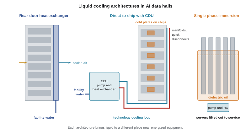
A rear-door heat exchanger replaces the back door of a rack with a coil through which water flows. Hot air leaving the servers passes through the coil and is cooled before it returns to the room. Passive doors rely on the server fans; active doors have their own fans. Rear doors can handle racks of perhaps 20 to 50 kW or more, depending on design, and they keep the liquid outside the servers, but they bring water, piping and hoses to the back of every rack they serve. Cedar Ridge uses rear doors on one row in Hall 1 and on some Hall 2 racks to remove the heat that cold plates do not capture.
Direct-to-chip cold plates
Direct-to-chip cooling, also called direct liquid cooling, mounts cold plates on the hottest components: accelerators, processors and sometimes memory and voltage regulators. Coolant from the TCS flows through fine channels in each cold plate and carries away most of the server's heat, commonly cited as 70 to 80 percent or more, while fans and room air remove the rest. Each server connects to vertical manifolds in the rack through flexible hoses with quick disconnect couplings, designed to seal both sides when unplugged so that a server can be removed without draining the loop. The rack manifolds connect to the CDU through supply and return piping, which in a slab-floor hall like Cedar Ridge Hall 2 runs overhead or at the end of rows.
Most direct-to-chip systems in 2026 are single-phase: the coolant stays liquid. Two-phase direct-to-chip systems pump a refrigerant or dielectric fluid that boils in the cold plate, absorbing heat as latent heat, and condense it elsewhere. They can remove more heat with less flow but involve refrigerants or engineered fluids under pressure, with hazards closer to those of refrigeration systems.
Immersion cooling
Immersion cooling submerges whole servers in a dielectric fluid, a liquid that does not conduct electricity. In single-phase immersion, servers stand vertically in an open tank of fluid, usually a synthetic hydrocarbon or other engineered oil; pumps circulate the fluid through a heat exchanger connected to the facility loop. In two-phase immersion, a fluorinated fluid with a low boiling point boils at the hot components, the vapour rises to a condenser coil above the fluid, and the condensed liquid drips back. Two-phase tanks must be sealed carefully to limit vapour loss.
Immersion handles very high densities and removes almost all server heat, but it changes how people work. Servers must be lifted out of the fluid for service, dripping fluid; floors near tanks can become slippery; tanks are heavy and must be placed on floors that can carry them; and the fluid itself has properties, such as combustibility for hydrocarbons or vapour hazards for fluorinated fluids, that must be managed. Cedar Ridge has a small single-phase immersion pilot pod of four tanks in Hall 2.
| Architecture | Liquid near IT | Typical coolant | Main worker hazards |
|---|---|---|---|
| Rear-door heat exchanger | In the rack door, outside servers | Facility water, sometimes with glycol | Leaks from coils and hoses onto floor and power cables; hinge and hose stress |
| Single-phase direct-to-chip | Inside servers, in cold plates and hoses | Treated water or propylene glycol mixture with inhibitors | Leaks at quick disconnects and hoses near energized parts; chemical contact; pressure |
| Two-phase direct-to-chip | Inside servers | Refrigerant or dielectric fluid | Pressurized fluid, refrigerant release, cold burns, vapour in confined areas |
| Single-phase immersion | Servers submerged in open tanks | Synthetic hydrocarbon or other dielectric oil | Slips, skin contact, heavy dripping lifts, combustible fluid, tank weight |
| Two-phase immersion | Servers submerged in sealed tanks | Fluorinated dielectric fluid | Vapour exposure, decomposition at high temperature, PFAS concerns |
Temperatures, pressures and flows
Liquid cooling loops run warmer than traditional chilled water. ASHRAE classifies facility water for liquid cooling into classes by maximum supply temperature, such as W32, W40 and W45, meaning supply water up to about 32, 40 or 45 °C (90, 104 or 113 °F), and higher for some designs. TCS supply temperatures in AI deployments are often in a similar range, with return temperatures about 10 °C (18 °F) higher. These temperatures are not dangerous to touch for brief contact, but return piping and spilled coolant can be uncomfortably hot, and a jet of warm coolant from a failed fitting is a scald and splash hazard.
TCS loops typically operate at modest pressures, a few bar (several tens of psi), limited by the ratings of hoses, cold plates and quick disconnects. Facility water loops can operate at higher pressures, especially in tall buildings. Even modest pressure can produce a strong jet from a cracked fitting, and stored pressure remains in a loop after its pumps stop, until it is relieved through the proper valves.
The program below uses Q = ṁ × cp × ΔT to estimate the coolant flow needed for racks of different powers, comparing water with a 25 percent propylene glycol mixture, which has a lower specific heat and slightly higher density. It also estimates the total heat in the Cedar Ridge Hall 2 liquid-cooled rows. The fluid properties are rounded typical values.
# Coolant flow needed to carry rack heat: Q = m_dot * cp * dT (teaching values).
fluids = {  # name: (cp in kJ/(kg K), density in kg/L)
    "water": (4.18, 0.99),
    "PG25 (25% propylene glycol)": (3.90, 1.02),
}
dT = 10.0                                   # K temperature rise across the rack
for kw in (40, 80, 130):
    for name, (cp, rho) in fluids.items():
        m_dot = kw / (cp * dT)              # kg/s
        lpm = m_dot / rho * 60              # L/min
        print(f"{kw:3} kW rack, {name:28}: {lpm:6.1f} L/min ({lpm/3.785:5.1f} US gal/min)")
# Hall 2 liquid-cooled rows (invented): 2 rows x 16 racks at 100 kW average,
# with 80% of heat to liquid.
racks, avg_kw, liquid_share = 32, 100, 0.80
q_liquid = racks * avg_kw * liquid_share
cp, rho = fluids["PG25 (25% propylene glycol)"]
flow = q_liquid / (cp * dT) / rho * 60
print(f"Hall 2: {q_liquid:.0f} kW to liquid needs about {flow:,.0f} L/min of PG25 at dT {dT:.0f} K")40 kW rack, water : 58.0 L/min ( 15.3 US gal/min) 40 kW rack, PG25 (25% propylene glycol) : 60.3 L/min ( 15.9 US gal/min) 80 kW rack, water : 116.0 L/min ( 30.6 US gal/min) 80 kW rack, PG25 (25% propylene glycol) : 120.7 L/min ( 31.9 US gal/min) 130 kW rack, water : 188.5 L/min ( 49.8 US gal/min) 130 kW rack, PG25 (25% propylene glycol) : 196.1 L/min ( 51.8 US gal/min) Hall 2: 2560 kW to liquid needs about 3,861 L/min of PG25 at dT 10 K
A single 130 kW rack needs about 190 litres (50 gal) of water-based coolant per minute, and the two invented Hall 2 rows need several thousand litres per minute in total. Those flows explain why a failed hose or quick disconnect in a liquid-cooled row can release a large volume quickly, and why CDUs have leak detection, pressure monitoring and automatic isolation. Lesson 11 returns to leak volumes.
Installing and commissioning liquid cooling in live halls
Liquid cooling is often installed in halls that are already running, so installation work brings hot work, heavy lifts, pressure testing and chemicals into the white space. Typical stages are: installing piping and CDUs; pressure testing the piping, usually with water or an inert gas at a test pressure above the operating pressure; flushing to remove debris, oil and welding residue; filling with coolant and purging air; adding inhibitors and checking water chemistry; and commissioning the controls, leak detection and alarms. Each stage has hazards. Pneumatic pressure tests store much more energy than hydrostatic tests at the same pressure and need exclusion zones. Flushing and filling involve hoses and temporary connections that can come loose. Treatment chemicals are concentrated and corrosive. Hot work for steel piping may be needed near protected rooms and detectors.
These activities are managed with methods of procedure, as HSE-320 Lesson 9 described, and with permits for hot work, pressure testing and chemical handling. The fire protection impairment process applies where detection must be isolated for hot work or dust.
Who owns what
Liquid cooling blurs the old line between facility and IT. A leak at a quick disconnect on a customer's server is in IT equipment, but the coolant may come from an operator-owned CDU, run through customer-owned manifolds, and drip onto an operator-owned floor beside operator-owned power cables. Sites need a clear agreement on who may connect and disconnect what, who monitors leak detection, who responds to alarms, who supplies and tests coolant, and who has authority to isolate a loop that serves many customers. At Cedar Ridge, the operator owns the FWS and CDUs and the customer owns everything downstream of the CDU outlet valves, but only operator-trained technicians may operate CDU valves.
Worked problem
Planning a CDU installation in Hall 2
Cedar Ridge plans to add a fifth CDU to Hall 2 to support two new rows of AI racks. The work includes connecting to the existing overhead facility water mains, a pneumatic pressure test of the new piping, flushing and filling with PG25, and commissioning. The hall is live and half occupied. What hazards should the method of procedure address?
Show solution
- Hot work or mechanical connection to live facility water mains: isolation and draining of the section, hot work permit and fire watch if welding, detection impairment planned with the fire protection contractor.
- Heavy lift of the CDU into position: rigging plan, route protection and floor loading checks (HSE-219 and HSE-320 Lesson 8).
- Pneumatic pressure test: exclusion zone, controlled pressurization, test gauge and relief device, and consideration of a hydrostatic test instead to reduce stored energy.
- Flushing and filling: secure temporary hoses, spill containment and absorbents, safety data sheets for PG25 and inhibitors, eye protection and gloves, eyewash available.
- Electrical: protect nearby energized equipment from splashes, route hoses away from power distribution, and agree what to do if a leak reaches power cables.
- Commissioning: test leak detection and automatic isolation before connecting customer equipment, and confirm alarm routing to the operations desk.
Answer: The method of procedure should cover isolation and hot work on live mains, the heavy lift, pressure testing energy, chemical handling and spill control during filling, protection of energized equipment, and commissioning of leak detection before customer racks are connected.
Common mistakes
MistakeAssuming liquid cooling only involves water at the edge of the room.
InsteadRecognize that coolant now flows through racks and servers beside energized equipment.
MistakeConnecting or disconnecting coolant hoses without authorization because quick disconnects look simple.
InsteadFollow the site rules on who may operate couplings and valves, and the manufacturer’s procedure.
MistakeAssuming a loop is safe once its pumps stop.
InsteadRelieve stored pressure through the proper valves before opening any part of the loop.
MistakeUsing a pneumatic pressure test without an exclusion zone.
InsteadTreat pneumatic tests as high stored energy, use exclusion zones or choose hydrostatic testing.
MistakeLeaving responsibility for liquid cooling alarms unclear between operator and customer.
InsteadAgree ownership, monitoring and response for every part of the loop in writing.
Summary and key terms
- AI racks of about 40 to more than 100 kW exceed what air can remove, so liquid carries heat from the chips.
- Heat carried follows Q = ṁ × cp × ΔT; water carries far more heat per volume than air.
- Most systems separate a facility water system from a technology cooling system through a coolant distribution unit.
- Rear-door heat exchangers, direct-to-chip cold plates and immersion tanks place liquid at different points near IT equipment.
- Single-phase direct-to-chip with water-based coolant dominates new AI deployments; two-phase systems were slowed by PFAS phase-outs.
- Loops run warm, at a few bar, with large flows; stored pressure remains after pumps stop.
- Installation in live halls involves hot work, heavy lifts, pressure tests and chemicals, and ownership must be clear.
- Cold plate
- A metal plate with internal channels mounted on a chip so that coolant can carry away its heat.
- Coolant distribution unit (CDU)
- Equipment that circulates the technology cooling loop and exchanges heat with the facility loop.
- Dielectric fluid
- A liquid that does not conduct electricity, used in immersion cooling.
- Facility water system (FWS)
- The building cooling water loop connected to the central plant.
- Quick disconnect
- A coupling that seals both sides when disconnected so equipment can be removed without draining the loop.
- Rear-door heat exchanger
- A water coil in a rack door that cools air leaving the servers.
- Technology cooling system (TCS)
- The loop that carries coolant through IT equipment from a CDU.
Practice problems
Work each problem on paper first, then reveal the answer to check.
Roughly how much heat can air practically remove from a rack?
Show answer
About 20 to 30 kW.
What equation gives the heat carried by a coolant?
Show answer
Q = ṁ × cp × ΔT.
What are the FWS and the TCS?
Show answer
The facility water system from the central plant, and the technology cooling system loop through IT equipment.
What does a CDU do?
Show answer
It circulates the TCS and transfers its heat to the FWS (or air) without mixing them, with filters, expansion tank, sensors and controls.
Why do quick disconnects matter for safety?
Show answer
They allow servers to be removed without draining, but they are leak points near energized equipment and must be operated correctly.
What is the difference between single-phase and two-phase immersion?
Show answer
Single-phase fluid stays liquid and is pumped through a heat exchanger; two-phase fluid boils and condenses above the tank.
What does the ASHRAE class W40 mean?
Show answer
Facility water supply up to about 40 °C (104 °F).
About how much water-based coolant does a 130 kW rack need at a 10 K rise?
Show answer
About 190 litres (50 gal) per minute.
Why are pneumatic pressure tests more hazardous than hydrostatic tests?
Show answer
Compressed gas stores much more energy than water at the same pressure.
Why must ownership of liquid cooling be agreed in writing at colocation sites?
Show answer
Loops cross operator and customer equipment, so responsibility for operation, monitoring and response must be clear.
Lesson quiz · 5 questions
Score 60% or more to complete this lesson.
Create a free account to save your progress, take quizzes and earn a certificate.