
ELE-480 · Lesson 9 of 12 · 22 min
Transformer protection
T1 is the most expensive single piece of equipment at Lincoln Road. A replacement 25 MVA power transformer costs well over a million dollars and can take a year or more to deliver, so a fault that destroys it leaves the station on a mobile unit or on its neighbours for a long time. Internal faults in transformers, a turn-to-turn short in a winding, a breakdown to the tank or a fault in the tap changer, start small and grow quickly as the arc decomposes the oil and generates gas. Fast, sensitive protection limits the damage to something repairable. At the same time, transformers produce currents that look like faults but are not, most famously the inrush when they are energized, and the protection must ride through them. This lesson shows how Nadine and Leo set the protection for T1.
Faults and abnormal conditions
Transformer protection must deal with internal faults, through faults and abnormal operating conditions. Internal faults include winding-to-ground and winding-to-winding faults, turn-to-turn faults, core faults and faults in the bushings, leads and tap changer. Through faults are faults outside the transformer, on the 25 kV bus or a feeder, whose current flows through the transformer and stresses its windings mechanically and thermally even though the transformer is healthy. Abnormal conditions include overload, overexcitation, loss of cooling and low oil level. The protection package for T1 addresses all three.
| Device | Function | Protects against |
|---|---|---|
| 87T | Percentage differential with harmonic restraint | Internal faults, fast and selective |
| 63 / sudden pressure | Rapid rise of gas pressure in the tank | Internal arcing faults, including small turn faults |
| Gas accumulation relay | Slow build-up of gas (conservator transformers) | Incipient faults and overheating |
| 50/51 high side, 51 low side | Overcurrent | Backup for internal faults and uncleared through faults |
| 51N or 51G on the neutral | Ground overcurrent | Ground faults on the 25 kV side; backup for feeders |
| 24 | Volts per hertz | Overexcitation |
| 49 and temperature devices | Thermal | Overload and loss of cooling |
The differential principle
Differential protection compares the currents entering and leaving the protected equipment. In a healthy transformer, after allowing for the turns ratio and the phase shift, the current in equals the current out, apart from a small magnetizing current. During an internal fault the difference, the operating current, becomes large. Differential protection is inherently selective, because it responds only to faults inside the zone bounded by its CTs, so it needs no coordination with other devices and can trip with no intentional delay.
Applying it to a transformer is harder than to a line or bus, for four reasons. The currents on the two sides differ by the turns ratio, and the CT ratios available never match it exactly. The delta-wye connection shifts the phase by 30°. A tap changer alters the ratio by up to about ±10 %. And magnetizing inrush appears on one side only, as an apparent internal fault. Each needs a remedy.
Older schemes corrected the phase shift by connecting the CTs on the wye side of the transformer in delta, and the CTs on the delta side in wye, which also removed zero-sequence current from the wye-side measurement. Numerical relays let all CTs be wired in wye and do the correction in software: they apply matrices that shift the phase and remove zero-sequence current, and they scale each side by a tap value equal to its full-load secondary current, so that the relay works in per unit of transformer rating.
import math, cmath
# T1: 25 MVA, 138 / 24.94 kV, delta-wye; CTs 200/5 (HV) and 800/5 (LV), wye-connected, relay compensates the shift
S = 25e6
Ihv = S/(math.sqrt(3)*138e3); Ilv = S/(math.sqrt(3)*24.94e3)
tap1, tap2 = Ihv/40, Ilv/160
print(f"full load: HV {Ihv:5.1f} A ({tap1:.3f} A sec), LV {Ilv:5.1f} A ({tap2:.3f} A sec)")
# Through fault on the 25 kV bus with the tap changer at its extreme (+10 %) and CT errors in the same direction
Ithru = 5618/Ilv                                # per unit of transformer rating
for tapdev, cterr in ((0.10, 0.0), (0.10, 0.05), (0.10, 0.10)):
    i1 = Ithru*(1 + tapdev)*(1 + cterr); i2 = Ithru
    iop = abs(i1 - i2); ires = (i1 + i2)/2
    print(f"tap +{tapdev:.0%}, CT error {cterr:.0%}: operate {iop:5.2f} pu, restraint {ires:5.2f} pu, ratio {iop/ires:5.1%}")
print("a 30 % slope with a 0.3 pu minimum pickup restrains all three cases")
# Second-harmonic content of a magnetizing inrush pulse train versus a fault current with DC offset
N = 256
def harm(samples, h):
    return abs(sum(x*cmath.exp(-2j*math.pi*h*k/N) for k, x in enumerate(samples)))*2/N
inrush, fault = [], []
for k in range(N):
    th = 2*math.pi*k/N
    flux = 1.0 - math.cos(th) + 0.8          # residual flux plus switching at a voltage zero
    inrush.append(max(flux - 1.6, 0)*8.0)    # current flows only while the core is saturated
    fault.append(math.sin(th - 1.4) + math.sin(1.4)*math.exp(-th/6))
for name, w in (('inrush', inrush), ('internal fault', fault)):
    r = harm(w, 2)/harm(w, 1)
    print(f"{name:15s} second harmonic {r:6.1%} of fundamental -> {'restrain' if r > 0.15 else 'trip'}")
# Overexcitation: volts per hertz during an islanded hydro start-up
for v, f in ((1.00, 60), (1.05, 60), (1.05, 57), (1.10, 55)):
print(f"V = {v:.2f} pu at {f} Hz: V/Hz = {v/(f/60):.3f} pu")full load: HV 104.6 A (2.615 A sec), LV 578.7 A (3.617 A sec) tap +10%, CT error 0%: operate 0.97 pu, restraint 10.19 pu, ratio 9.5% tap +10%, CT error 5%: operate 1.50 pu, restraint 10.46 pu, ratio 14.4% tap +10%, CT error 10%: operate 2.04 pu, restraint 10.73 pu, ratio 19.0% a 30 % slope with a 0.3 pu minimum pickup restrains all three cases inrush second harmonic 31.9% of fundamental -> restrain internal fault second harmonic 10.0% of fundamental -> trip V = 1.00 pu at 60 Hz: V/Hz = 1.000 pu V = 1.05 pu at 60 Hz: V/Hz = 1.050 pu V = 1.05 pu at 57 Hz: V/Hz = 1.105 pu V = 1.10 pu at 55 Hz: V/Hz = 1.200 pu
With 200:5 CTs on the 138 kV side and 800:5 on the 25 kV side, T1's full-load secondary currents are 2.615 A and 3.617 A, and those become the relay's two tap settings. A tap mismatch, the difference between the CT ratio and the transformer ratio, is fully compensated by the taps. What cannot be compensated is the tap changer: when it moves away from its nominal position, the actual ratio changes, and a through fault produces a differential current proportional to the tap deviation.
Percentage restraint
For the largest through fault on the 25 kV bus, 5.62 kA or 9.7 times rated current, the program shows the differential current that a healthy transformer produces: 0.97 pu with the tap changer at +10 %, 1.50 pu if the CTs also err by 5 % in the same direction, and 2.04 pu with 10 % CT error. A relay with a fixed pickup low enough to catch small internal faults would trip for those external faults. Percentage differential relays solve this by making the pickup grow with the through current. They compute a restraint current, typically the average or the larger of the currents in the windings, and trip only when the operating current exceeds a fraction of it, the slope, as well as a minimum pickup.
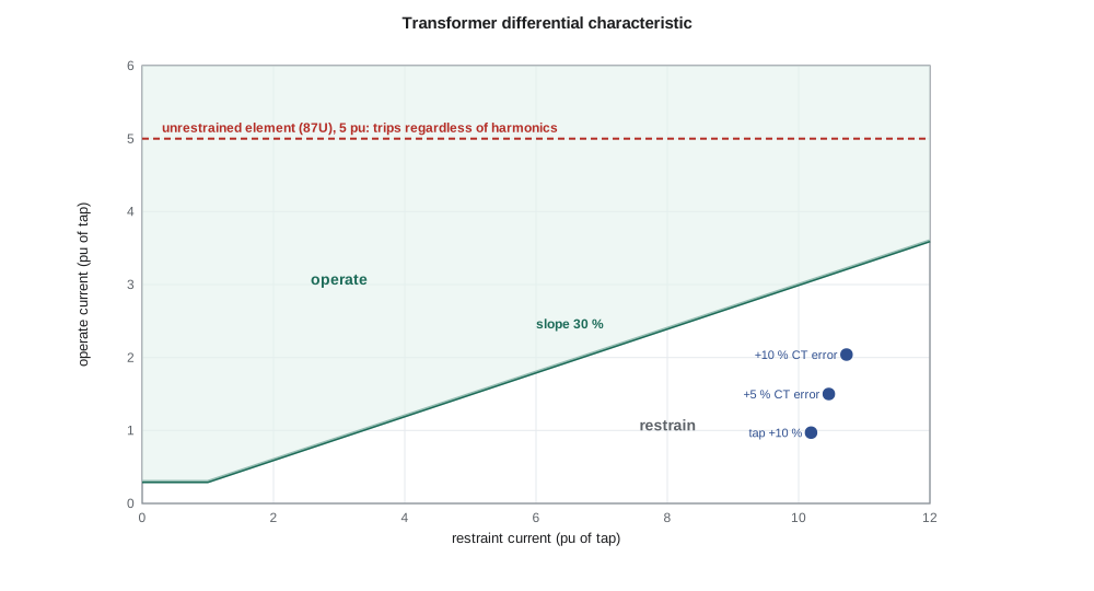
Nadine sets a minimum pickup of 0.3 pu and a slope of 30 %. The ratios from the program, 9.5 %, 14.4 % and 19.0 %, all fall below 30 %, so the relay restrains for every through-fault case. Many relays use a dual slope, a gentle slope at low currents for sensitivity and a steeper one above a breakpoint where CT saturation becomes likely, which gives extra security for heavy external faults.
Magnetizing inrush
When a transformer is energized, its core flux must start from whatever remanent value it had and follow the applied voltage. If the switching instant is unfavourable, the flux can reach roughly twice its normal peak plus the remanence, deep into saturation, and the transformer draws a magnetizing current of several times its rated current for a few cycles, decaying over seconds. That current flows on the energized side only, so the differential relay sees it entirely as operating current. Sympathetic inrush, drawn when a parallel transformer is energized, and recovery inrush after a nearby fault is cleared, produce the same effect.
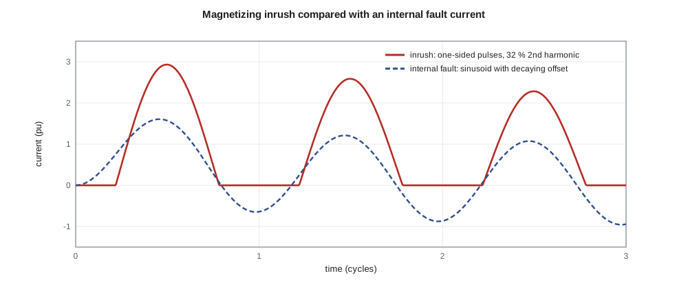
Inrush has a distinctive shape: the current flows only while the core is saturated, in one-sided pulses with long gaps, which makes it rich in even harmonics, especially the second. Internal fault currents are nearly sinusoidal. The program computes the second harmonic of a model inrush waveform as about 32 % of the fundamental, and that of a fault current with DC offset as about 10 %. Relays restrain or block the differential element when the second harmonic exceeds a setting, often 15 to 20 % of the fundamental, and some also use the fourth harmonic or the shape of the waveform, detecting the flat gaps directly. Modern transformers built with high-grade, low-loss steel can produce inrush with less second harmonic than older ones, which is one reason relays combine several methods.
An unrestrained differential element, 87U, set well above any possible inrush, trips without harmonic restraint for severe internal faults, whose currents might contain harmonics from CT saturation. Nadine sets it at 5 pu of tap. Overexcitation produces strong fifth-harmonic current, so many relays also block on fifth harmonic, leaving overexcitation to the volts-per-hertz element.
Sudden pressure and gas relays
A turn-to-turn fault involving a few turns produces a large current in the shorted turns but a small change in the terminal currents, sometimes below the differential relay's minimum pickup. It does, however, produce an arc in the oil, which generates gas and a pressure wave. Sudden pressure relays detect the rate of rise of pressure and trip within a cycle or two, independent of the electrical measurements. Transformers with conservator tanks use a gas accumulation relay in the pipe to the conservator, which alarms on slow gas build-up from incipient faults and trips on a surge of oil. These mechanical relays complement the differential relay; together they cover a wider range of faults than either alone.
Overexcitation
The flux in a transformer core is proportional to voltage divided by frequency. Raising the voltage or lowering the frequency increases the flux; beyond about 1.05 to 1.10 pu volts per hertz the core begins to saturate, magnetizing current rises sharply and stray flux heats structural parts that are not designed to carry it. Overexcitation occurs during generator start-up at reduced speed, after load rejection, or in islanded systems with poor voltage control. The program shows that 1.05 pu voltage at 57 Hz gives 1.105 pu volts per hertz, and 1.10 pu at 55 Hz gives 1.20 pu. A volts-per-hertz element (24) alarms at a low level and trips on an inverse-time curve that matches the transformer manufacturer's withstand limits.
Through-fault capability and backup
Transformers are designed to withstand through faults for limited times, and IEEE and CSA standards give through-fault capability curves that combine thermal limits with mechanical limits for frequent faults. Overcurrent relays on the transformer must protect it within those curves and also back up the feeder relays, which means coordinating with the slowest feeder setting. The transformer's 25 kV overcurrent relay at Lincoln Road is set above the feeder relays with a coordination interval at the maximum feeder fault, and the 138 kV overcurrent relay backs it up in turn. A neutral overcurrent element on T1's grounded-wye neutral backs up the feeder ground elements; as lesson 2 showed, the 138 kV side cannot see 25 kV ground faults as zero-sequence current.
Worked problem
Will the relay trip for a turn fault?
A turn-to-turn fault in T1's 25 kV winding shorts 2 % of the turns. The change in terminal currents is estimated at about 0.2 pu of rating, while the transformer carries 0.6 pu load. With a 0.3 pu minimum pickup and 30 % slope, does the differential element operate?
Show solution
- Operate current: about 0.2 pu, the change in terminal currents.
- Restraint: about the load current, 0.6 pu, so 30 % of it is 0.18 pu, but the minimum pickup of 0.3 pu governs.
- 0.2 pu is below 0.3 pu, so the differential element does not operate.
- The arc in the oil generates gas and a pressure rise, so the sudden pressure relay is the protection that clears this fault.
Answer: No; the differential element misses this small turn fault, and the sudden pressure relay must catch it.
Common mistakes
MistakeSetting a differential relay's pickup without considering the tap changer.
InsteadOff-nominal taps create differential current for through faults; percentage restraint and slope must cover it.
MistakeForgetting to remove zero-sequence current from the wye-side measurements.
InsteadAn external ground fault would otherwise produce false differential current.
MistakeRelying on second-harmonic restraint alone for modern transformers.
InsteadLow-loss cores can produce low-harmonic inrush; combine methods.
MistakeAssuming differential protection covers all internal faults.
InsteadSmall turn faults may need sudden pressure or gas relays.
Summary and key terms
- Transformer protection covers internal faults, through faults and abnormal conditions.
- Differential protection compares currents in and out after ratio and phase-shift compensation.
- Percentage restraint raises the pickup with through current to tolerate tap changers and CT errors.
- Inrush is rich in second harmonic; relays restrain on harmonics and use an unrestrained element for severe faults.
- Sudden pressure and gas relays catch small internal faults the differential may miss.
- Volts-per-hertz protection guards against overexcitation.
- Overcurrent and neutral relays back up the differential and protect against uncleared through faults.
- Percentage differential
- A differential relay whose pickup rises with the restraint current.
- Slope
- The ratio of operate to restraint current above which a percentage differential relay trips.
- Tap (relay)
- The scaling current that converts a winding's secondary current to per unit of rating.
- Magnetizing inrush
- The large one-sided current drawn when a transformer is energized.
- Harmonic restraint
- Blocking or restraining differential operation when harmonic content indicates inrush.
- Sudden pressure relay
- A relay that trips on a rapid rise of gas pressure in a transformer tank.
- Overexcitation
- Excess core flux caused by high voltage or low frequency.
Practice problems
Work each problem on paper first, then reveal the answer to check.
T1's full-load current is 578.7 A on the 25 kV side. What is the secondary current with 800:5 CTs?
Show answer
3.617 A.
Why does a numerical relay remove zero-sequence current from the wye-side currents?
Show answer
So external ground faults, whose zero-sequence current does not pass to the delta side, do not create differential current.
A through fault gives 1.5 pu operate and 10.5 pu restraint. Does a 30 % slope restrain?
Show answer
Yes: 14 % is below 30 %.
What harmonic is the classic indicator of inrush?
Show answer
The second.
Calculate V/Hz at 1.08 pu voltage and 58 Hz.
Show answer
1.08/(58/60) ≈ 1.12 pu.
What catches turn faults too small for the differential element?
Show answer
The sudden pressure or gas accumulation relay.
Lesson quiz · 5 questions
Score 60% or more to complete this lesson.
Create a free account to save your progress, take quizzes and earn a certificate.