
ELE-480 · Lesson 3 of 12 · 21 min
Instrument transformers
A relay is only as good as the signals it receives. At Lincoln Road the feeder relays measure currents of up to 5.87 kA at 14.4 kV to ground, and the 138 kV line relays measure voltages of 80 kV to ground. No relay could connect to those directly, so instrument transformers reduce them to standard secondary values: 5 A (or 1 A) for current transformers at rated primary current, and 120 V phase to phase (69.3 V phase to neutral) for voltage transformers. They also isolate the relays and the people who work on them from the high voltage. Ravi tells Leo that more protection problems start in the CT circuits than in the relays, and that by the end of this lesson he should be able to say whether a CT will tell the truth during a fault.
How a current transformer works
A CT is a transformer whose primary is the power conductor itself, usually passing once through a toroidal core, and whose secondary is a winding of many turns around that core. With a turns ratio of 1:N, the secondary current is the primary current divided by N, less a small error. The error comes from the magnetizing current: some of the primary ampere-turns are needed to magnetize the core rather than to drive secondary current. The magnetizing current depends on the voltage the CT must develop to push secondary current through the burden, the total impedance of the secondary circuit: the CT's own winding resistance, the leads to the relay and the relay itself.
A CT secondary must never be left open while primary current flows. With no secondary current to oppose it, the full primary ampere-turns magnetize the core, and the secondary voltage rises to thousands of volts in sharp peaks each half cycle, enough to injure a person and destroy insulation. Test switches and shorting terminal blocks are installed in every CT circuit so that technicians can short the secondary before disconnecting a relay. Ravi makes Leo say the rule aloud before he is allowed near a test switch: short first, then open.
Accuracy classes
Protection CTs are specified differently from metering CTs. A metering CT must be accurate at normal load, a fraction of a percent at currents near rating; a protection CT must stay reasonably accurate at fault currents many times rating. In Canada, CTs are built to CSA standards, which have adopted the IEC instrument transformer series, and many utilities also specify the IEEE C57.13 relay accuracy classes familiar across North America. An IEEE C-class rating such as C400 means that the CT can deliver 20 times its rated secondary current (100 A for a 5 A CT) into a standard burden of 4 Ω, a terminal voltage of 400 V, with a ratio error of no more than 10 %. The C indicates that the rating can be calculated from the CT's construction because its leakage flux is negligible, as in toroidal bushing CTs. The IEC equivalent is written as an accuracy limit, such as 5P20 or 10P20: 5 or 10 % composite error at 20 times rated current into the rated burden.
Multi-ratio bushing CTs have taps on their secondary winding, such as 100/200/300/400/500/600:5. The C rating applies to the full winding; on a lower tap the number of turns is smaller, and the available voltage falls in proportion. A 600:5 C400 CT used on its 300:5 tap is effectively a C200. Choosing a low tap to make a relay more sensitive therefore weakens the CT, a trade-off protection engineers check every time.
The excitation curve and saturation
Each CT has an excitation curve, plotted on log-log axes, showing the secondary voltage the core can support against the magnetizing current it draws. On the lower part of the curve the magnetizing current is tiny and the CT is accurate. Above the knee point, a small increase in voltage requires a large increase in magnetizing current; the core is saturating, and the secondary current becomes a distorted, reduced copy of the primary. IEEE defines the knee point as the point where the curve's slope is 45° on log-log axes with equal decades; IEC uses a different definition, a 10 % voltage increase requiring a 50 % increase in magnetizing current, so the two knee voltages are not directly comparable.
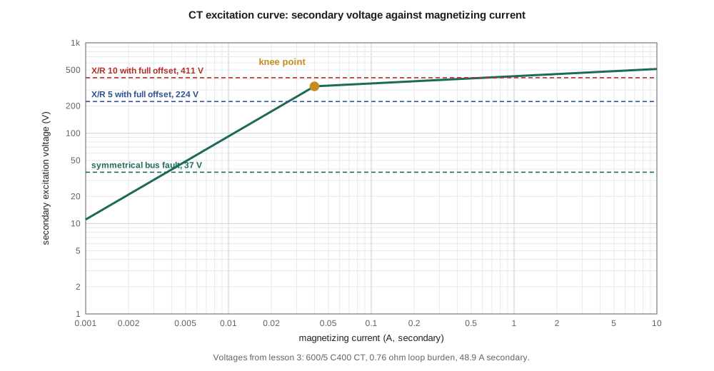
Saturation has two causes. Symmetrical saturation occurs when the steady fault current is so large that even its sinusoidal component requires a voltage above the knee. Asymmetrical saturation is caused by the DC offset of the fault current: the DC component builds up flux in the core in one direction, and the core can saturate after a few cycles even if the AC component alone would not saturate it. Remanent flux left in the core from a previous fault or a DC test can add to the offset flux and make saturation happen sooner.
A widely used criterion for avoiding saturation, given in IEEE guides, compares the voltage the CT can deliver with the voltage needed to carry the fault current, including the effect of the offset:
Here I_f is the secondary fault current. When the inequality holds, the CT reproduces the fully offset fault current without saturating. When it does not, the CT will saturate at some point, and the time to saturation can be estimated from the X/R ratio and the margin.
Checking the feeder CT
Leo checks the CT on feeder F2: a 600:5 multi-ratio bushing CT, C400 on its full winding, used at 600:5. Its winding resistance is about 0.35 Ω. The relay is 60 m from the breaker in the control building, connected with 10 AWG leads, about 0.39 Ω out and back, and the numerical relay adds only 0.02 Ω. The largest fault current through the CT is the 5.87 kA bus ground fault from lesson 2.
import math
# Feeder CT: 600/5 multi-ratio, C400 (full winding), used at the 600/5 tap
ratio = 600/5
Rct = 0.0025*120 + 0.05                  # secondary winding resistance, about 2.5 milliohm/turn plus leads inside
lead = 2*60*0.00328                      # 60 m one way of 10 AWG (about 3.3 milliohm/m), out and back
relay = 0.02                             # numerical relay burden, ohms
Zb = Rct + lead + relay
If = 5865                                # largest fault through the CT, A (25 kV bus line-to-ground, lesson 2)
Is = If/ratio
for xr in (0, 5, 10):
    Vneed = Is*Zb*(1 + xr)
    print(f"X/R {xr:2d}: secondary {Is:5.1f} A, burden {Zb:.2f} ohm, voltage needed {Vneed:6.0f} V  ->  {'within C400' if Vneed <= 400 else 'beyond C400: expect saturation'}")
# C400 means 400 V at 20 x rated (100 A) into the standard 4 ohm burden with ratio error under 10 %
print(f"\nC400 rating check: 20 x 5 A x 4 ohm = {20*5*4} V")
# Time to saturate (approximate) for full offset: Ts = -(X/omega/R) ln(1 - (Ks - 1)/(X/R))
w = 2*math.pi*60
for xr in (5, 10):
    Ks = 400/(Is*Zb)                     # how far the rated voltage exceeds the symmetrical need
    if Ks - 1 >= xr: print(f"X/R {xr}: CT does not saturate"); continue
    Ts = -(xr/w)*math.log(1 - (Ks - 1)/xr)
    print(f"X/R {xr}: saturation begins after about {Ts*1000:4.1f} ms")
# Voltage transformer ratio for 25 kV line-to-ground connection
print(f"\nVT ratio 14 400 : 120 = {14400/120:.0f}:1; 14.4 kV primary gives {14400/120:.0f} V secondary")X/R 0: secondary 48.9 A, burden 0.76 ohm, voltage needed 37 V -> within C400 X/R 5: secondary 48.9 A, burden 0.76 ohm, voltage needed 224 V -> within C400 X/R 10: secondary 48.9 A, burden 0.76 ohm, voltage needed 411 V -> beyond C400: expect saturation C400 rating check: 20 x 5 A x 4 ohm = 400 V X/R 5: CT does not saturate X/R 10: saturation begins after about 94.6 ms VT ratio 14 400 : 120 = 120:1; 14.4 kV primary gives 120 V secondary
The total burden is 0.76 Ω, and the secondary fault current is 48.9 A. The symmetrical component needs only 37 V. With full DC offset at X/R = 5 it needs 224 V, within the C400 rating; at X/R = 10 it needs 411 V, just beyond it, and the estimate says saturation would begin after about 95 ms. Because the feeder's instantaneous element operates within about one cycle, well before 95 ms, Nadine accepts the CT. If the program had shown saturation within a few milliseconds, she would have had to choose a higher ratio, a higher accuracy class, larger leads or a relay algorithm that tolerates saturation.
The check also shows why a numerical relay's tiny burden matters. An electromechanical overcurrent relay could present several ohms at its lowest tap, which would have multiplied the required voltage several times over and made saturation likely. Modern relays have almost removed the relay from the burden calculation, leaving the CT winding and the leads as the main terms; long lead runs in large stations deserve attention for that reason.
What saturation does to relays
A saturated CT delivers current in short, distorted pulses whose fundamental component is smaller than the true current. Overcurrent relays operate more slowly than their settings say, or not at all for marginal cases, which can upset coordination. Distance relays measure too high an impedance and underreach. Differential relays are most at risk: if one CT saturates during an external fault while the others do not, the relay sees a false differential current and may trip for a fault outside its zone. Lessons 9 and 11 show how percentage restraint and high-impedance bus schemes deal with that problem.
Voltage transformers
Voltage transformers come in two main forms. Inductive VTs are small transformers with a high-voltage primary winding, used at distribution and subtransmission voltages. Capacitor voltage transformers (CVTs), used at transmission voltages, divide the line voltage with a stack of capacitors and then use a small transformer and a tuning reactor to produce the secondary voltage; they are cheaper than inductive VTs at high voltages and can double as coupling capacitors for power-line carrier. At Lincoln Road the 25 kV bus has inductive VTs with a ratio of 14 400:120, or 120:1, connected phase to ground, and each 138 kV line has CVTs.
CVTs have a transient problem that protection engineers must respect. When a close-in fault suddenly collapses the primary voltage, the energy stored in the capacitors and the tuning reactor makes the secondary voltage ring down over a cycle or two instead of collapsing at once. A distance relay that measured impedance from that transient voltage could overreach, seeing a fault as closer than it is. Modern distance relays detect conditions in which CVT transients could cause overreach and briefly slow down their Zone 1 operation, and engineers sometimes reduce Zone 1 reach slightly on lines with strong sources behind them.
VT secondary circuits are protected by fuses or small breakers, and a blown VT fuse removes voltage from the relay. A distance or directional relay that suddenly loses its voltage would see what looks like a fault, so relays include loss-of-potential logic that detects a voltage drop without a corresponding change in current and blocks the voltage-dependent elements, raising an alarm instead of tripping.
Polarity, grounding and wiring
CTs and VTs have polarity marks, and relays that compare currents or measure direction depend on correct polarity. Every CT circuit must be grounded at exactly one point: grounding provides safety if the primary-to-secondary insulation fails, and a single point avoids circulating currents through the ground grid that would corrupt the measurement. During commissioning Ravi checks ratio, polarity and burden on every CT, and once the circuit is in service he confirms with load current that each relay measures the phase angles he expects.
Worked problem
Can the 300:5 tap be used?
To make a sensitive ground relay pick up at a lower primary current, Leo suggests moving the F2 CTs to their 300:5 tap. With the same leads and relay, will the CT still handle the 5.87 kA fault with X/R = 5 and full offset?
Show solution
- On the 300:5 tap the CT has half the turns, so its effective rating is about C200, and its winding resistance is about half, roughly 0.18 Ω.
- Secondary current doubles to 5865/60 = 97.8 A, and the burden becomes 0.18 + 0.39 + 0.02 = 0.59 Ω.
- \[V = 97.8 \times 0.59 \times (1 + 5) \approx 346\ \text{V}\]
- 346 V is well above the 200 V the tap can deliver, so the CT would saturate early in the fault.
Answer: No; the lower tap weakens the CT too much. A more sensitive relay setting is the better route.
Common mistakes
MistakeOpening a CT secondary to remove a relay while the circuit is energized.
InsteadShort the secondary first; an open CT secondary develops dangerous voltages.
MistakeAssuming a C400 rating holds on every tap.
InsteadThe rating applies to the full winding and falls in proportion on lower taps.
MistakeChecking only the symmetrical fault current.
InsteadDC offset can multiply the required voltage by (1 + X/R).
MistakeGrounding a CT circuit at several points for extra safety.
InsteadGround each CT circuit at one point only to avoid circulating currents.
Summary and key terms
- CTs and VTs reduce primary quantities to standard secondary values and isolate relays.
- Never open an energized CT secondary; short it first.
- A C400 CT delivers 20 times rated current at 400 V with no more than 10 % ratio error; lower taps derate it.
- Saturation begins above the knee point and is made worse by DC offset and remanent flux.
- Check V_s ≥ I_f (R_ct + R_lead + Z_relay)(1 + X/R) to avoid saturation.
- CVTs produce transients that can make distance relays overreach; relays compensate.
- Loss-of-potential logic blocks voltage-based elements when a VT fuse blows.
- Current transformer (CT)
- An instrument transformer that produces a secondary current proportional to the primary current.
- Burden
- The total impedance connected to a CT secondary, including leads and relay.
- Knee point
- The point on the excitation curve above which the core begins to saturate.
- Accuracy class C400
- An IEEE relay class: 20 times rated current at 400 V with at most 10 % ratio error.
- Remanent flux
- Flux left in a CT core after a fault or test, which can hasten saturation.
- Capacitor voltage transformer (CVT)
- A voltage transformer using a capacitive divider, common at transmission voltages.
- Loss of potential
- Loss of VT voltage at a relay, detected and used to block voltage-based elements.
Practice problems
Work each problem on paper first, then reveal the answer to check.
What is the secondary current of a 600:5 CT carrying 2400 A?
Show answer
20 A.
What effective accuracy class does a 1200:5 C800 CT have on its 600:5 tap?
Show answer
About C400.
A CT carries 40 A secondary into a 1.0 Ω burden with X/R = 8. What voltage avoids saturation?
Show answer
40 × 1.0 × 9 = 360 V.
Why does a numerical relay help CT performance?
Show answer
Its burden is tiny, so the CT needs less voltage.
What does loss-of-potential logic do?
Show answer
Detects a lost VT voltage without a current change and blocks distance and directional elements.
Why are CT circuits grounded at one point only?
Show answer
To provide safety without creating circulating ground currents.
Lesson quiz · 5 questions
Score 60% or more to complete this lesson.
Create a free account to save your progress, take quizzes and earn a certificate.