
ELE-480 · Lesson 8 of 12 · 21 min
Pilot schemes and communications
Stepped distance protection has one unavoidable weakness. Zone 1 at each end covers only 80 to 90 % of the line, so a fault near either end is inside Zone 1 at the near terminal but only in Zone 2 at the far terminal. The near end clears in a few cycles; the far end waits for its Zone 2 timer. For the last 10 to 20 % of the line at each end, together 20 to 40 % of the line, one terminal trips slowly. On the Lincoln Road to Hollis line that delay would be about 0.37 s, and on Larchmont's more heavily loaded lines a planning study has shown that clearing times above about 0.15 s could threaten the stability of the Larchmont Falls generators for some outage combinations. The cure is to let the relays at the two ends talk to each other. A protection scheme that uses a communication channel between terminals is called a pilot scheme, from the old pilot wires that once carried the signals, and is designated device 85.
The idea of a pilot scheme
Each terminal knows only what it measures, but together the two terminals know exactly where a fault is. If both ends see a fault in the forward direction, it must be on the line between them. If one end sees it forward and the other sees it behind, it is outside the line. Pilot schemes exchange simple messages, a permission, a block or a transfer trip, or the actual measured currents, so that each end can make that judgement for faults anywhere on the line and trip both ends at high speed.
Direct and permissive transfer trip
The simplest scheme is direct underreaching transfer trip (DUTT): when Zone 1 at either end operates, it trips its own breaker and sends a trip signal that trips the remote breaker directly. It speeds up clearing of the remote end but depends entirely on the channel's security, because a false signal trips the line. Permissive underreaching transfer trip (PUTT) adds supervision: the received signal trips the remote breaker only if the remote relay's own overreaching element, typically Zone 2, also sees a forward fault.
Permissive overreaching transfer trip (POTT) is the most widely used permissive scheme. Each end sends a permissive signal when its overreaching element, Zone 2 or a forward directional ground element, sees a fault. Each end trips when its own overreaching element operates and it receives a permissive signal from the other end. For an internal fault both ends see forward, both send, both receive, and both trip in a few cycles plus the channel delay. For an external fault beyond the remote bus, the remote end sees the fault behind it and does not send, so the local end, despite its Zone 2 operating, does not receive permission and waits for its Zone 2 timer as backup.
POTT needs extra logic for special cases. Current reversal on parallel lines, when the opening of one breaker reverses the current in the healthy parallel line, can momentarily make both ends of the healthy line see forward; a reversal-guard timer holds back the permissive signal after a reverse fault was seen. A weak-infeed end, where there is little or no source and the relay sees too little current, cannot send permission on its own, so echo logic returns the received signal if the local relay saw no reverse fault, and weak-infeed tripping logic can trip the weak end using undervoltage.
Directional comparison blocking
Directional comparison blocking (DCB) works the other way round. Each end sends a block signal when its reverse-looking element sees a fault behind it. Each end trips when its forward overreaching element operates and no block signal has arrived within a short coordination time. For an internal fault, no one sees a reverse fault, no block is sent, and both ends trip after the coordination time. For an external fault, the end nearest the fault sees it behind and sends a block, which arrives in time to stop the far end from tripping.
The great advantage of DCB is dependability: the channel is not needed to trip for internal faults, so a channel damaged by the very fault it should help clear does not prevent tripping. That made DCB the natural partner of on-off power-line carrier, whose signal travels on the faulted line itself and may be attenuated by the fault. The price is security: if a block signal is lost during an external fault, the far end trips the healthy line. The coordination timer must be long enough for the remote block to start and arrive, which adds a few milliseconds to every internal-fault clearing.
# Clearing times for a fault 10 % from the Hollis end of the 40 km line (inside Hollis Zone 1, Zone 2 at Lincoln Road)
cyc = 1000/60
relay_z1, relay_z2_detect, breaker = 1.0*cyc, 1.2*cyc, 3.0*cyc
z2_delay = 300
step  = relay_z2_detect + z2_delay + breaker           # Lincoln Road waits for its Zone 2 timer
chan  = {'optical channel (direct)': 6, 'digital microwave': 10, 'power-line carrier (FSK)': 12}
print(f"step distance at Lincoln Road: {step:6.0f} ms")
for n, d in chan.items():
    pott = relay_z2_detect + d + 2 + breaker            # permissive trip: own Zone 2 plus received permission
    print(f"POTT over {n:28s}: {pott:6.0f} ms")
# DCB: the local relay must wait long enough for a block signal from the remote end to arrive
remote_block_pickup, chan_delay, margin = 4, 12, 4     # ms; carrier blocking scheme
ctd = remote_block_pickup + chan_delay + margin
print(f"\nDCB coordination timer: {remote_block_pickup} + {chan_delay} + {margin} = {ctd} ms")
print(f"DCB internal-fault clearing: {relay_z2_detect + ctd + breaker:.0f} ms")
# Line current differential: line charging current versus a sensitive pickup
import math
C_per_km = 9.0e-9                                       # farads per km, typical 138 kV overhead line
Ic = 138e3/math.sqrt(3)*2*math.pi*60*C_per_km*40
print(f"\ncharging current of the 40 km line: {Ic:4.0f} A per phase")
for slope_pickup in (0.3*800, 0.1*800):
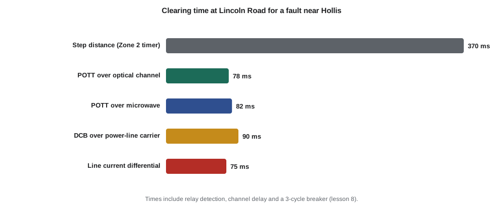
print(f"differential pickup {slope_pickup:4.0f} A is {slope_pickup/Ic:4.1f} times the charging current")step distance at Lincoln Road: 370 ms POTT over optical channel (direct) : 78 ms POTT over digital microwave : 82 ms POTT over power-line carrier (FSK) : 84 ms DCB coordination timer: 4 + 12 + 4 = 20 ms DCB internal-fault clearing: 90 ms charging current of the 40 km line: 11 A per phase differential pickup 240 A is 22.2 times the charging current differential pickup 80 A is 7.4 times the charging current
The program puts numbers on the comparison for a fault 10 % from the Hollis end. Step distance clears the Lincoln Road end in about 370 ms. POTT clears it in 78 to 84 ms depending on the channel; DCB, with a 20 ms coordination timer made up of the remote block pickup time, the 12 ms carrier channel delay and a margin, clears it in about 90 ms. Either scheme brings the whole line within the 0.15 s that the stability study requires.
Line current differential
Line current differential protection (87L) applies the differential principle of lesson 9 to a line whose ends are kilometres apart. Each relay samples its currents and sends them, as phasors or samples with time stamps, to the relay at the other end over a digital channel. Each relay then compares local and remote currents: for a fault outside the line the current entering one end leaves the other, and the differential current is small; for a fault on the line the currents add. Differential protection needs no voltage transformers, is unaffected by power swings, infeed or mutual coupling, and covers high-resistance faults that distance elements miss.
Its requirements lie in the channel. The two ends' currents must be aligned in time, either by measuring the channel's round-trip delay and assuming it is the same in both directions, or by time-stamping samples with satellite-synchronized clocks. Channels whose send and receive paths have different delays, which can happen when a switched network reroutes one direction, introduce an apparent phase shift and a false differential current, so relays monitor asymmetry and protection engineers prefer dedicated optical fibre paths. Line charging current also appears as differential current; the program shows that for the 40 km line it is only about 11 A, small compared with practical pickups of 80 to 240 A, but on long cables and extra-high-voltage lines it must be compensated.
Larchmont runs an optical ground wire on the Hollis line, so Nadine chooses line current differential as the primary scheme, with POTT over the same fibre and step distance as backup. Lincoln Road to Grafton has only a leased digital circuit, so it gets POTT with distance and directional ground elements.
Channels
| Channel | Typical delay | Strengths | Weaknesses |
|---|---|---|---|
| Dedicated optical fibre | A few ms | Immune to electrical interference; high bandwidth for differential | Cost of fibre where none exists |
| Digital microwave or multiplexed network | About 5 to 15 ms | Shares infrastructure; long distances | Path changes and asymmetric delays must be managed |
| Power-line carrier | About 8 to 20 ms | Uses the protected line itself | Signal may be attenuated by the fault; limited bandwidth |
| Leased telecom circuit | Varies | No utility infrastructure needed | Outside the utility's control; reliability varies |
Whatever the channel, the scheme must be designed for its failure. Relays monitor the channel continuously, alarm on loss, and fall back to step distance or to a different channel. Permissive schemes lose speed but not security when the channel fails; blocking schemes keep speed but lose security. The choice between them is partly a judgement about which failure the system can tolerate better.
IEC 61850 and digital substations
Inside the substation, numerical relays increasingly exchange signals over Ethernet rather than copper wires. The IEC 61850 standard defines how protection devices describe their data and exchange it. Its GOOSE messages (generic object-oriented substation events) carry trip, block and status signals between relays in a few milliseconds, repeated rapidly after each change so that a lost packet does not matter. Sampled values messages carry digitized CT and VT measurements from merging units in the switchyard to relays in the control building, replacing long copper runs with fibre. A breaker failure initiate, a blocking signal for a bus scheme or a transfer trip to a remote station can all be GOOSE messages.
Digital substations change how protection is tested and maintained. A test set can inject sampled values and watch GOOSE replies, and test modes can isolate one relay without disturbing the others. They also make the substation network part of the protection system, which brings it under the same discipline of design review, redundancy and cybersecurity that lesson 12 discusses.
Worked problem
Setting the DCB coordination timer
A DCB scheme uses power-line carrier with a channel delay of 12 ms. The remote relay's reverse element and carrier start take 4 ms, and Larchmont adds a 4 ms margin. What coordination timer is needed, and what is the internal-fault clearing time if Zone 2 detection takes 20 ms and the breaker 50 ms?
Show solution
- \[t_{coord} = 4 + 12 + 4 = 20\ \text{ms}\]
- For an internal fault the local relay must still wait for the timer after its forward element operates.
- \[t_{clear} = 20 + 20 + 50 = 90\ \text{ms}\]
Answer: A 20 ms coordination timer, giving about 90 ms clearing for internal faults.
Common mistakes
MistakeAssuming POTT trips if the channel fails during an internal fault.
InsteadWithout permission, POTT falls back to step distance timing; it does not trip at high speed.
MistakeForgetting current-reversal guards on parallel lines.
InsteadBreaker opening on one line can briefly make both ends of the other see forward.
MistakeUsing a switched network with unequal send and receive delays for line differential without monitoring.
InsteadAsymmetric delay creates false differential current.
MistakeChoosing DCB without considering lost block signals.
InsteadDCB is dependable but less secure; a lost block during an external fault trips the healthy line.
Summary and key terms
- Pilot schemes use a channel so both ends of a line trip at high speed for faults anywhere on it.
- POTT trips on the local forward overreaching element plus a received permissive signal.
- DCB trips on the local forward element unless a block arrives within a coordination time.
- Permissive schemes are secure but need the channel to trip; blocking schemes are dependable but need it to restrain.
- Line current differential compares currents at both ends and needs time-aligned data over a digital channel.
- Channels include fibre, microwave, power-line carrier and leased circuits; schemes must handle channel loss.
- IEC 61850 GOOSE and sampled values carry protection signals and measurements over substation networks.
- Pilot scheme (85)
- Protection that uses a communication channel between line terminals.
- POTT
- Permissive overreaching transfer trip: trip on local forward element plus received permission.
- DCB
- Directional comparison blocking: trip on local forward element unless a block signal is received.
- Coordination timer
- The delay in a DCB scheme that allows a remote block signal to arrive.
- Line current differential (87L)
- A scheme comparing currents at the line ends over a digital channel.
- Echo logic
- Returning a received permissive signal from a weak-infeed terminal that sees no reverse fault.
- GOOSE
- An IEC 61850 message that carries fast event signals between devices over Ethernet.
Practice problems
Work each problem on paper first, then reveal the answer to check.
Why does step distance clear end-zone faults slowly at one terminal?
Show answer
The fault is in Zone 2, not Zone 1, at the far terminal, which must wait for the Zone 2 timer.
In POTT, what must happen for a terminal to trip at high speed?
Show answer
Its overreaching element operates and it receives a permissive signal.
Why is DCB considered dependable?
Show answer
It does not need the channel to trip for internal faults.
What causes false differential current in a line differential scheme with a switched channel?
Show answer
Unequal send and receive delays.
The charging current of a line is 11 A and the pickup is 240 A. Is compensation needed?
Show answer
Not for this short overhead line.
What does a GOOSE message carry?
Show answer
Fast event signals such as trips, blocks and status between devices.
Lesson quiz · 5 questions
Score 60% or more to complete this lesson.
Create a free account to save your progress, take quizzes and earn a certificate.