
ELE-480 · Lesson 5 of 12 · 22 min
Distribution feeder coordination
Feeder F2 runs 18 km from Lincoln Road through a suburban subdivision and out into farmland. Four kilometres from the substation a line recloser, R2, divides it into a protected urban section and a rural section where trees and lightning cause most of the faults. Single-phase laterals branch off the main line, each protected by a fuse at its tap. Most faults on the rural section are temporary: a branch brushes a conductor, a bird bridges an insulator, lightning flashes over and the arc goes out as soon as the current is interrupted. Coordination is the job of making the feeder relay, the recloser and the fuses work together so that temporary faults cause only a brief interruption, permanent faults disconnect only the faulted section, and every device is backed up by the one upstream.
The devices on a feeder
Fuses are the simplest protective devices: a fusible element that melts when current exceeds its rating for long enough. Distribution cutout fuses are described by two curves. The minimum melting curve gives the time at which the element starts to melt, and the total clearing curve gives the time by which the arc is extinguished and the current interrupted. Common link types include K (fast) and T (slow) links, whose numbers give the continuous current rating; a 65T link carries 65 A continuously and has a relatively slow, steep curve. A fuse interrupts once and must be replaced by a line crew.
A recloser is a self-contained circuit breaker with its own controls that trips on overcurrent and automatically recloses after a short dead time, typically repeating up to three or four times before locking out. Modern reclosers use electronic controls with programmable curves, often one or two fast operations followed by one or two delayed operations. A sectionalizer is a switch that cannot interrupt fault current; it counts the interruptions made by an upstream recloser while it sees fault current, and opens during the dead time after a set count, isolating a permanent fault beyond it so that the recloser's next reclose succeeds.
The substation feeder breaker, controlled by the feeder relay and often a reclosing relay (79), is the last line of defence on the feeder and the backup for everything downstream.
Coordination principles
Two devices coordinate when the one nearer the fault, the protecting device, always operates before the one further upstream, the protected or backup device, for every fault current that both can see. On a time-current plot, that means the protecting device's clearing curve lies below and to the left of the backup device's operating curve over the full range of fault currents at the protecting device's location, with a margin.
The margins depend on the devices. Between two relays, the coordination time interval allows for the downstream breaker's interrupting time, relay overtravel and tolerances: 0.3 s is a common figure for numerical relays, 0.2 s with fast breakers, 0.4 s with electromechanical relays. Between a relay or recloser and a downstream fuse, the backup device must not operate before the fuse's total clearing time. Between a fast recloser operation and a fuse, the recloser must clear before the fuse is damaged, which by long practice means before 75 % of the fuse's minimum melting time, so that heating during the recloser's operations does not weaken the element. All curves are drawn on a common voltage base, here 25 kV.
Fuse saving and fuse blowing
Two philosophies compete for faults on fused laterals. In fuse saving, the recloser's fast curve, or the substation relay's instantaneous element, trips before the lateral fuse can melt. If the fault was temporary, the reclose restores service to everyone, including the lateral, and no crew is needed. If the fault is permanent, the recloser's next operations use its delayed curve, slow enough for the fuse to clear first, so only the lateral is lost. The cost is that every customer on the feeder sees a momentary interruption for every fault on any lateral.
In fuse blowing, the fast operations are disabled or set slower than the fuse, so the lateral fuse clears every fault on its lateral, temporary or not. Customers on the rest of the feeder see only a voltage sag, but the lateral's customers wait for a crew even for temporary faults. As sensitive electronic loads have made momentary interruptions more costly to customers, many utilities have moved toward fuse blowing in suburban areas while keeping fuse saving on rural feeders where crews take longer to arrive. Larchmont uses fuse saving beyond R2 and fuse blowing on the urban section.
Coordinating feeder F2
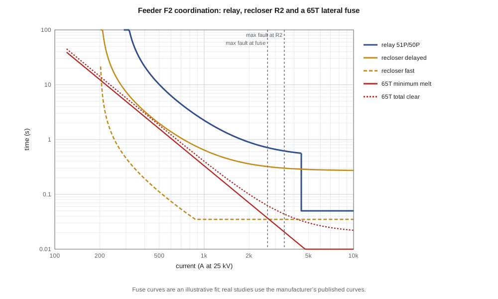
Lesson 4's first setting for the feeder relay, an extremely inverse curve at time dial 2.0, operates in 0.15 s for the 3.44 kA maximum fault at the recloser. R2's delayed curve takes about 0.30 s at that current, so the substation relay would trip first and black out the whole feeder for a fault the recloser should have handled. Leo has to slow the feeder relay at high currents. He changes it to the very inverse curve with a time dial of 5.0, keeping the 288 A pickup, and gives the recloser a 200 A pickup with an inverse delayed curve at time dial 1.5 and an extremely inverse fast curve at time dial 0.10, limited to a minimum response of 35 ms.
import math
# Feeder F2 fault levels along the line (from the lesson 2 model)
S, V = 100e6, 24.94e3; Ib = S/(math.sqrt(3)*V); Zb = V**2/S
z1s = complex(0.00520, 0.0520); zt = 0.36j
def fault(km):
    z1 = z1s + zt + complex(0.11, 0.40)*km/Zb; z0 = zt + complex(0.33, 1.35)*km/Zb
    return abs(1/z1)*Ib, abs(3/(2*z1 + z0))*Ib
def ieee(td, M, A, B, p): return td*(A/(M**p - 1) + B) if M > 1 else float('inf')
U2, U3, U4 = (5.95, 0.180, 2.0), (3.88, 0.0963, 2.0), (5.67, 0.0352, 2.0)
relay    = lambda I: ieee(5.0, I/288, *U3)                 # substation relay 51P: U3, 288 A, TD 5.0
rec_fast = lambda I: max(ieee(0.10, I/200, *U4), 0.035)    # recloser R2 fast curve: 200 A pickup
rec_slow = lambda I: ieee(1.5, I/200, *U2)                 # recloser R2 delayed curve: U2, TD 1.5
# 65T fuse link: illustrative log-log straight-line fit; real studies use the manufacturer's curves
fuse_mm = lambda I: 10*(220/I)**2.25
fuse_tc = lambda I: 1.15*fuse_mm(I) + 0.02
for name, km in (('substation bus', 0), ('recloser R2 (4 km)', 4), ('lateral fuse (7 km)', 7), ('lateral end (10 km)', 10)):
    i3, ig = fault(km); print(f"{name:21s} 3ph {i3:5.0f} A   SLG {ig:5.0f} A")
Imax = max(fault(4))
print(f"\nRelay vs recloser at {Imax:.0f} A: relay {relay(Imax):.2f} s, recloser delayed {rec_slow(Imax):.2f} s, interval {relay(Imax) - rec_slow(Imax):.2f} s")
print("\n  I (A)   fast  0.75xMM   fuse TC  delayed   fuse saving  fuse vs delayed")
for I in (400, 800, 1200, 1600, 2000, 2400, 2656):
    fs = rec_fast(I) < 0.75*fuse_mm(I); fd = fuse_tc(I) < rec_slow(I)
    print(f"{I:6d} {rec_fast(I):7.3f} {0.75*fuse_mm(I):8.3f} {fuse_tc(I):9.3f} {rec_slow(I):8.3f}   {'yes' if fs else 'NO ':>8s}      {'yes' if fd else 'NO'}")
# Reach of a 50P instantaneous element set at 1.3 x the recloser's maximum fault
inst = 1.3*Imax; km = 0
while fault(km)[0] > inst: km += 0.1
print(f"\n50P set at {inst:.0f} A covers three-phase faults out to about {km:.1f} km")substation bus 3ph 5618 A SLG 5865 A recloser R2 (4 km) 3ph 3437 A SLG 2679 A lateral fuse (7 km) 3ph 2656 A SLG 1898 A lateral end (10 km) 3ph 2162 A SLG 1469 A Relay vs recloser at 3437 A: relay 0.62 s, recloser delayed 0.30 s, interval 0.32 s I (A) fast 0.75xMM fuse TC delayed fuse saving fuse vs delayed 400 0.193 1.954 3.016 3.245 yes yes 800 0.041 0.411 0.650 0.865 yes yes 1200 0.035 0.165 0.273 0.525 yes yes 1600 0.035 0.086 0.152 0.412 yes yes 2000 0.035 0.052 0.100 0.360 yes yes 2400 0.035 0.035 0.073 0.332 NO yes 2656 0.035 0.028 0.062 0.321 NO yes 50P set at 4468 A covers three-phase faults out to about 1.7 km
The program confirms the relay-recloser coordination: at 3437 A the relay takes 0.62 s and the recloser's delayed curve 0.30 s, an interval of 0.32 s. At lower currents the interval only grows, because the very inverse relay curve rises faster than the inverse recloser curve as current falls.
For the lateral fuse, the results are mixed and typical. The fuse clears before the recloser's delayed curve at every current up to the maximum fault at the fuse location, 2656 A, so permanent faults on the lateral blow only the fuse. But the fast curve saves the fuse only up to about 2 kA. Above roughly 2.4 kA the fuse melts before the recloser's fastest operation can clear, so close-in faults on laterals near the tap will blow the fuse even though fuse saving is enabled. That is not a setting error; it is the physics of a fuse and a breaker that takes a couple of cycles to open. Leo records the fuse saving limit in the coordination report so that the operators understand why a lateral fuse sometimes blows during a lightning storm.
| Check | Requirement | Result on F2 |
|---|---|---|
| Relay over recloser delayed curve | At least 0.3 s at the recloser's maximum fault | 0.62 s − 0.30 s = 0.32 s |
| Fuse over recloser delayed curve | Fuse total clearing below the delayed curve | Yes, up to 2656 A |
| Recloser fast curve saves fuse | Fast curve below 75 % of fuse minimum melt | Up to about 2 kA |
| Relay sees end-of-feeder faults | Minimum fault at least twice pickup | 1.2 kA ≥ 2 × 288 A |
| Instantaneous does not overreach R2 | Pickup at least 1.3 × fault at R2 | 4.47 kA covers the first 1.7 km |
Instantaneous elements on the feeder
Larchmont sets the feeder relay's instantaneous element at 1.3 times the maximum fault at the recloser, 4.47 kA, which the program finds covers three-phase faults out to about 1.7 km. Close-in faults on that first section are cleared in about 80 ms instead of 0.6 s, which matters both for the cable and switchgear at the substation and, as lesson 12 will show, for the arc flash energy that a worker at the switchgear could be exposed to.
Reclosing practice
Larchmont's typical sequence on overhead feeders is one fast and two delayed operations, with dead times of about 0.5 s, 2 s and 10 s before lockout. The first reclose is fast because most temporary faults clear within a fraction of a second; longer later dead times give a tree branch time to burn off or fall clear. Underground cable feeders are not reclosed, because cable faults are almost always permanent and reclosing into them causes more damage. Reclosing is also blocked when a crew is working on the line under a hot-line hold order, so that a fault caused by the work is not re-energized.
Distributed generation and the old assumptions
Overcurrent coordination on distribution feeders rests on one assumption: fault current flows outward from the substation. Distributed generation such as the solar plant on feeder F3 breaks that assumption, because the plant also feeds current into faults, from the other direction. It can reduce the current seen by the substation relay for faults beyond it, make a neighbouring feeder's relay trip for a fault on another feeder, and keep a fault energized during the recloser's dead time, defeating reclosing. Lesson 6 introduces the directional elements that solve some of these problems, and lesson 12 studies the solar plant on F3 in detail.
Worked problem
Can a 40T fuse replace the 65T?
A lateral's load has fallen, and Leo considers a 40T link, whose curves lie at roughly 60 % of the 65T currents. Would fuse saving cover more or less of the lateral, and what new risk appears?
Show solution
- A smaller link melts at lower current for any given time, so its 75 % minimum-melt curve meets the recloser's 35 ms fast curve at a lower current, roughly 0.6 × 2.4 kA ≈ 1.4 kA.
- Fuse saving would therefore work only up to about 1.4 kA instead of 2 kA, so more lateral faults would blow the fuse.
- The smaller link also has less margin over cold-load and transformer inrush current on the lateral, so nuisance blowing becomes more likely.
Answer: A smaller fuse shrinks the fuse saving range and raises the risk of nuisance blowing; the 65T stays.
Common mistakes
MistakeChecking coordination at one current only.
InsteadCheck over the whole range of fault currents both devices can see, especially at the maximum fault at the downstream device.
MistakeUsing the fuse's minimum melting curve for backup checks.
InsteadUpstream devices must wait for the fuse's total clearing time; the fast recloser must beat 75 % of minimum melt.
MistakeExpecting fuse saving to work for every lateral fault.
InsteadAbove a certain current the fuse melts before any breaker can open.
MistakeReclosing underground cable feeders.
InsteadCable faults are nearly always permanent; reclosing adds damage.
Summary and key terms
- Feeders use relays, reclosers, sectionalizers and fuses that must coordinate.
- The protecting device must clear before the backup device operates, with a margin, at all currents both see.
- Relay-to-relay intervals of about 0.3 s; a fast recloser must beat 75 % of the fuse's minimum melting time.
- Fuse saving clears temporary lateral faults with a reclose; fuse blowing avoids momentary interruptions for the rest of the feeder.
- Fuse saving fails at high currents where the fuse melts faster than the breaker can open.
- Instantaneous elements speed clearing of close-in faults without overreaching the next device.
- Distributed generation undermines the assumption of one-way fault current.
- Recloser
- A self-contained breaker that trips on fault current and recloses automatically a set number of times.
- Sectionalizer
- A switch that counts upstream interruptions and opens during a dead time to isolate a permanent fault.
- Minimum melting curve
- The time-current curve at which a fuse element begins to melt.
- Total clearing curve
- The time-current curve at which a fuse has interrupted the current.
- Fuse saving
- Using fast breaker or recloser operations to clear lateral faults before the fuse melts.
- Fuse blowing
- Letting the lateral fuse clear all faults on its lateral.
- Coordination time interval
- The minimum time margin between a protecting device and its backup.
Practice problems
Work each problem on paper first, then reveal the answer to check.
At the recloser's maximum fault the relay takes 0.62 s and the recloser 0.30 s. Is the interval adequate?
Show answer
Yes: 0.32 s meets a 0.3 s requirement.
Why must the fast recloser curve be below 75 % of the fuse's minimum melting time?
Show answer
So the fuse element is not damaged by heating during the fast operations.
Name one advantage and one drawback of fuse saving.
Show answer
Advantage: temporary lateral faults clear without a crew. Drawback: all feeder customers see a momentary interruption.
What does a sectionalizer count?
Show answer
Interruptions by the upstream device while it has seen fault current.
Why is reclosing blocked during hot-line work?
Show answer
So a fault caused by the work is not re-energized.
How does distributed generation complicate feeder coordination?
Show answer
It feeds fault current from the other direction, changing what each relay sees.
Lesson quiz · 5 questions
Score 60% or more to complete this lesson.
Create a free account to save your progress, take quizzes and earn a certificate.