
ELE-480 · Lesson 2 of 12 · 22 min
Fault analysis for protection
Every protection setting starts from a fault study. Before Nadine will let Leo choose a pickup current or a time dial, she asks him for a table of fault currents at every point that matters: the 138 kV bus, the 25 kV bus, the recloser, the fused laterals and the far end of each feeder, for each type of fault, with the system at its strongest and at its weakest. ELE-380 built the tools for this, the per-unit system, the bus impedance matrix and symmetrical components. This lesson applies them with a protection engineer's questions in mind: how much current will each relay see, in which phases and which sequence quantities, and how small can the current get when a fault has resistance in it?
The four shunt faults
Four types of fault account for almost all faults on a three-phase system. A single-line-to-ground (SLG) fault, one phase in contact with ground, is by far the most common on overhead lines, often caused by lightning, contamination or vegetation; figures of 70 to 80 % of transmission faults are often quoted. Line-to-line (LL) faults and double-line-to-ground (DLG) faults follow, and balanced three-phase faults are the least common, often caused by a grounding clamp left on after maintenance or by a structure collapsing onto all three conductors. The three-phase fault is nevertheless the one engineers study first, because it is the easiest to calculate and usually gives the largest current, which sets the interrupting ratings of breakers.
Symmetrical components turn each unbalanced fault into a connection of the positive-, negative- and zero-sequence networks. For a three-phase fault only the positive-sequence network is involved. For an SLG fault the three networks connect in series, so I₁ = I₂ = I₀ and the fault current is 3I₀. For an LL fault the positive and negative networks connect in parallel with no zero-sequence current. For a DLG fault the negative and zero networks are in parallel with each other and in series with the positive network.
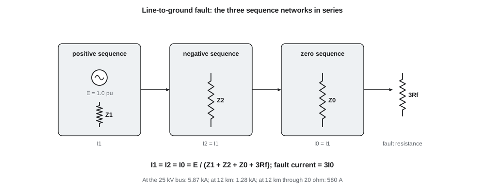
The zero-sequence network is where most surprises hide, because it depends on how equipment is grounded. Zero-sequence current needs a return path through ground and neutral connections. A delta winding blocks it from passing between the two sides of a transformer but circulates it inside the delta, and a grounded-wye winding passes it. T1 is delta on the 138 kV side and solidly grounded wye on the 25 kV side, so for faults on the 25 kV system it is a source of zero-sequence current, its own leakage impedance providing the path. That is why a line-to-ground fault on the 25 kV bus can produce more current than a three-phase fault there: Z₀ of the transformer is about equal to Z₁, but Z₀ does not include the source impedance behind the delta.
The Lincoln Road model
Larchmont's system planners supply the Thevenin equivalent at the Lincoln Road 138 kV bus: a three-phase fault there produces 8.0 kA with an X/R ratio of 10, and a line-to-ground fault produces 7.0 kA. Leo works on a 100 MVA base. T1 has 9 % impedance on its 25 MVA rating, or 0.36 pu on 100 MVA. The 25 kV feeder conductor has a positive-sequence impedance of about 0.11 + j0.40 Ω/km and a zero-sequence impedance of about 0.33 + j1.35 Ω/km, typical of a large overhead conductor with a multigrounded neutral. The base impedance at 24.94 kV is 6.22 Ω, so each kilometre adds about 0.018 + j0.064 pu.
import cmath, math
a = cmath.exp(2j*math.pi/3)
S = 100e6                                   # base MVA
V_hv, V_lv = 138e3, 24.94e3
Ib_lv = S/(math.sqrt(3)*V_lv); Ib_hv = S/(math.sqrt(3)*V_hv)
# Source at the 138 kV bus: 8.0 kA three-phase, X/R 10; zero-sequence from a 7.0 kA line-to-ground fault
I3 = 8.0e3/Ib_hv; z1s = (1/I3)*complex(math.cos(math.atan(10)), math.sin(math.atan(10)))
Ig = 7.0e3/Ib_hv; z0s = 3/Ig - 2*z1s
zt = 0.09*S/25e6*1j                          # 25 MVA, 9 % transformer, delta-wye grounded
zf1 = complex(0.11, 0.40)*12/(V_lv**2/S)     # 12 km of feeder, ohms per km
zf0 = complex(0.33, 1.35)*12/(V_lv**2/S)
def faults(z1, z2, z0, rf=0.0):
    zf = rf/(V_lv**2/S)
    i3 = 1/z1
    ig = 3/(z1 + z2 + z0 + 3*zf)
    ill = -1j*math.sqrt(3)/(z1 + z2)
    i1 = 1/(z1 + z2*(z0 + 3*zf)/(z2 + z0 + 3*zf)); i2 = -i1*(z0 + 3*zf)/(z2 + z0 + 3*zf); i0 = -i1 - i2
    idlg = i0 + a*a*i1 + a*i2               # phase b current, b-c-ground fault
    return abs(i3), abs(ig), abs(ill), abs(idlg), abs(3*i0)
for name, z1, z0 in (('25 kV bus', z1s + zt, zt), ('feeder end, 12 km', z1s + zt + zf1, zt + zf0)):
    r = faults(z1, z1, z0)
    print(f"{name:18s} 3ph {r[0]*Ib_lv/1e3:5.2f} kA  SLG {r[1]*Ib_lv/1e3:5.2f} kA  LL {r[2]*Ib_lv/1e3:5.2f} kA  DLG {r[3]*Ib_lv/1e3:5.2f} kA")
r = faults(z1s + zt + zf1, z1s + zt + zf1, zt + zf0, rf=20)
print(f"feeder end, 20 ohm fault: SLG {r[1]*Ib_lv:6.0f} A")
# What the 138 kV side sees for a 25 kV bus SLG fault (the delta-wye shifts sequences by 30 degrees and blocks zero sequence)
z1 = z1s + zt
i1 = 1/(2*z1 + zt)                         # SLG at the 25 kV bus: I1 = I2 = I0
i1h = i1*cmath.exp(1j*math.pi/6); i2h = i1*cmath.exp(-1j*math.pi/6)
for n, ih in (('A', i1h + i2h), ('B', a*a*i1h + a*i2h), ('C', a*i1h + a*a*i2h)):
    print(f"138 kV phase {n}: {abs(ih)*Ib_hv:6.0f} A")
print(f"25 kV faulted phase: {abs(3*i1)*Ib_lv:6.0f} A")25 kV bus 3ph 5.62 kA SLG 5.87 kA LL 4.87 kA DLG 5.73 kA feeder end, 12 km 3ph 1.92 kA SLG 1.28 kA LL 1.67 kA DLG 1.74 kA feeder end, 20 ohm fault: SLG 580 A 138 kV phase A: 612 A 138 kV phase B: 0 A 138 kV phase C: 612 A 25 kV faulted phase: 5865 A
At the 25 kV bus a three-phase fault gives 5.62 kA and a line-to-ground fault 5.87 kA, slightly more, as expected from the delta-wye transformer. Twelve kilometres out on a feeder the picture changes: the three-phase current falls to 1.92 kA, but the line-to-ground current falls further, to 1.28 kA, because the feeder's zero-sequence impedance is more than three times its positive-sequence impedance. Add 20 Ω of fault resistance, a modest value for a conductor lying on dry ground or a tree branch, and the ground fault current falls to 580 A. Ground faults with resistance are the hardest faults for distribution protection to see, and lesson 6 returns to them.
| Location | 3-phase | Line-to-ground | Line-to-line | Double-line-to-ground |
|---|---|---|---|---|
| 25 kV bus | 5.62 kA | 5.87 kA | 4.87 kA | 5.73 kA |
| Feeder, 12 km | 1.92 kA | 1.28 kA | 1.67 kA | 1.74 kA |
| Feeder, 12 km, 20 Ω to ground | — | 580 A | — | — |
The line-to-line value is always √3/2, or 87 %, of the three-phase value at the same point when Z₂ = Z₁, which holds for lines and transformers. Protection engineers use that ratio constantly: a phase overcurrent relay that must detect the smallest phase fault at the end of its zone is checked against the line-to-line current, not the three-phase current.
Maximum and minimum conditions
A fault study is run at least twice. Maximum fault conditions, with all generation in service and the strongest network configuration, give the largest currents, which are used to check equipment ratings, to set instantaneous elements so that they do not overreach, and to check coordination at the high-current end of the curves. Minimum fault conditions, with generators and lines out of service and with realistic fault resistance, give the smallest currents, which are used to check that every relay can still see the faults it must clear. A relay that is set above the minimum fault current at the end of its zone is not dependable, however well it coordinates.
At Lincoln Road the minimum condition is a 138 kV line out of service and Larchmont Falls offline. The planners' weak-source equivalent gives about 5.5 kA for a three-phase fault at the 138 kV bus. Leo reruns the study with that source and finds that the far end of feeder F2, 18 km out, produces a line-to-line fault of about 1.2 kA and a line-to-ground fault through 20 Ω of about 510 A. Those numbers will set limits on the pickup settings chosen in lessons 4 to 6.
What the other side of the transformer sees
A delta-wye transformer changes both the magnitude and the pattern of fault currents. Sequence currents pass through with a 30° phase shift, positive sequence one way and negative sequence the other, and zero-sequence current does not pass at all. The program shows the result for a line-to-ground fault on the 25 kV bus: the faulted phase carries 5.87 kA, but on the 138 kV side two phases each carry 612 A and the third carries nothing. Scaled by the voltage ratio, 612 A is 1/√3 of the 25 kV current. A relay on the 138 kV side that expected to see a phase current equal to the scaled fault current would underestimate it, and a 138 kV ground relay sees no ground current at all, because the delta blocks zero sequence.
This is why ground faults on the 25 kV system must be cleared by 25 kV ground relays, and why the transformer's backup protection on the 138 kV side has limited sensitivity to them. It is also why differential protection of a delta-wye transformer must compensate for the phase shift and remove zero-sequence current from the wye-side measurements, as lesson 9 shows.
Fault resistance and arcs
Real faults are rarely bolted. An arc between conductors has a voltage that is roughly proportional to its length, and its apparent resistance grows as the arc stretches in the wind. A fault to ground adds the resistance of the tree, the pole, the soil or whatever the conductor touches, which can range from a few ohms to hundreds of ohms. A downed conductor on dry asphalt or sand may draw so little current that no overcurrent relay can detect it, while still being a deadly hazard to anyone who approaches. Such high-impedance faults are a persistent problem for distribution utilities, and special detection algorithms that look for the irregular, arcing signature of the current have been developed, though none detects every case.
Fault resistance affects distance relays too: it adds a resistive component to the impedance the relay measures, which can make a fault appear outside the relay's reach. Lesson 7 shows how quadrilateral characteristics extend the resistive coverage of distance relays for exactly this reason.
DC offset and the X/R ratio
When a fault occurs, the current cannot jump instantly to its steady sinusoidal value, because the system inductance resists sudden change. Depending on the point on the voltage wave at which the fault begins, the current includes a decaying DC component. The time constant of that decay is L/R, or (X/R)/ω. With X/R = 10 at 60 Hz the time constant is about 27 ms, so the offset lasts for several cycles. The peak current in the first cycle can approach 2.5 times the RMS symmetrical value at high X/R. The DC offset does not change the fundamental-frequency phasor a numerical relay estimates once its filters have settled, but it can drive CTs into saturation, which lesson 3 examines, and it determines the asymmetrical ratings of breakers.
Worked problem
A fault at the end of feeder F2
Using the program's model, estimate the three-phase and line-to-line fault currents at 18 km on feeder F2 under maximum conditions.
Show solution
- Positive-sequence impedance to the fault: source and transformer 0.0052 + j0.412 pu plus 18 km × (0.0177 + j0.0643) pu = 0.324 + j1.569 pu.
- \[|Z_1| = \sqrt{0.324^2 + 1.569^2} = 1.602\ \text{pu}\]
- \[I_{3\phi} = \frac{1}{1.602} \times 2315\ \text{A} = 1445\ \text{A}\]
- \[I_{LL} = \frac{\sqrt{3}}{2} \times 1445 = 1251\ \text{A}\]
Answer: About 1.45 kA three-phase and 1.25 kA line to line; the minimum-condition line-to-line value of about 1.2 kA is what the feeder relay must still detect.
Common mistakes
MistakeUsing only the three-phase fault current for all settings.
InsteadLine-to-line, ground and resistive faults are smaller; dependability is checked against the smallest fault in the zone.
MistakeAssuming a delta-wye transformer passes ground current.
InsteadZero-sequence current does not pass through the delta; the high-voltage side sees two phases at 1/√3 of the scaled current.
MistakeIgnoring fault resistance on distribution ground faults.
InsteadTens of ohms can cut the current by more than half and hide the fault from a ground relay.
MistakeStudying only maximum conditions.
InsteadMinimum conditions decide whether every relay can still see the faults it must clear.
Summary and key terms
- Fault studies supply the currents that every protection setting depends on.
- SLG faults are the most common; three-phase faults usually give the largest current.
- Sequence networks connect in series for SLG faults, in parallel (1 and 2) for LL faults.
- A delta-wye grounded transformer is a zero-sequence source for faults on its wye side.
- Maximum conditions check ratings and overreach; minimum conditions check dependability.
- Fault resistance greatly reduces distribution ground fault currents.
- DC offset decays with time constant (X/R)/ω and can saturate CTs.
- Bolted fault
- A fault with zero impedance at the fault point.
- Symmetrical components
- Positive-, negative- and zero-sequence sets that represent unbalanced phasors.
- Zero-sequence network
- The network carrying in-phase currents that return through ground and neutrals.
- Minimum fault current
- The smallest current for a fault in a zone, used to check that relays can detect it.
- X/R ratio
- The ratio of reactance to resistance of the fault path, which sets the DC offset time constant.
- High-impedance fault
- A ground fault with so much resistance that overcurrent relays may not detect it.
- Thevenin equivalent
- A source and impedance that represent the rest of the system at a bus.
Practice problems
Work each problem on paper first, then reveal the answer to check.
The three-phase fault current at a point is 2.0 kA. Estimate the line-to-line current.
Show answer
About 1.73 kA (87 %).
Why can the line-to-ground current at the 25 kV bus exceed the three-phase current?
Show answer
The transformer's zero-sequence impedance excludes the source impedance behind its delta winding.
What happens to the 25 kV ground fault current at 12 km with 20 Ω of fault resistance?
Show answer
It falls from 1.28 kA to about 580 A.
Which fault condition is used to check that a relay can detect faults at the end of its zone?
Show answer
Minimum fault conditions.
What is the DC time constant for X/R = 15 at 60 Hz?
Show answer
15/377 ≈ 40 ms.
How much zero-sequence current flows on the 138 kV side for a 25 kV ground fault?
Show answer
None; the delta winding blocks it.
Lesson quiz · 5 questions
Score 60% or more to complete this lesson.
Create a free account to save your progress, take quizzes and earn a certificate.