
ELE-480 · Lesson 11 of 12 · 21 min
Bus protection, breaker failure and reclosing
A fault on a substation bus is rare but serious. Buses are short, enclosed or well shielded, and protected from lightning, so they fault far less often than lines; but when they do, the fault current is the highest anywhere in the station, every circuit connected to the bus feeds it, and clearing it means opening every one of those circuits. A bus fault left to remote backup would be cleared slowly by relays at other stations, disconnecting far more than the bus itself. A bus protection that tripped falsely would black out the whole station. Bus protection must therefore be fast, dependable and, above all, secure. This lesson covers bus protection at Lincoln Road, the breaker failure scheme that backs up every breaker in the station, and the reclosing that restores service after temporary faults.
Bus arrangements
How a bus is protected depends on how it is arranged. A single bus, like Lincoln Road's 25 kV bus, is simple and cheap, but a bus fault or bus maintenance takes every circuit out of service. Ring buses, breaker-and-a-half arrangements and double buses cost more breakers but let a bus fault or a breaker failure be isolated while most circuits stay in service; they are common at transmission voltages. Lincoln Road's 138 kV bus is a small ring, so each line and the transformer sit between two breakers and the ring's sections are protected by the overlapping line and transformer zones, while its 25 kV bus is a single bus with its own bus protection.
Why bus protection is difficult
Bus protection is usually a differential scheme: the currents in all the circuits connected to the bus should sum to zero unless there is a fault on the bus. The difficulty is CT saturation during external faults. For a fault just outside the bus on feeder F2, the current in F2's CT is the sum of the currents from every other source, the largest current any CT in the station carries. If F2's CT saturates while the others do not, its secondary current is too small, and a simple differential relay sees a large false differential current and trips the whole bus for a feeder fault. Every bus protection scheme is, in one way or another, a solution to that problem.
High-impedance bus differential
The high-impedance scheme, one of the oldest and still widely used, connects all the CTs in parallel at a junction and places a relay with a high impedance, typically a few thousand ohms, across the junction. During an external fault in which one CT saturates completely, that CT's magnetizing impedance collapses and it behaves as a short circuit through its winding resistance. The healthy CTs then drive their current through the leads and the saturated CT's winding, and the voltage across the relay is limited to that current times the winding and lead resistance of the saturated CT's loop. The relay is set above that voltage with a margin, so it does not operate. During an internal fault, all CTs push current into the high impedance and the voltage rises toward the CTs' knee points, far above the setting, and the relay operates. A voltage-limiting device protects the circuit from the very high voltages that internal faults would otherwise produce.
Here I_F/N is the secondary current of the largest external fault, R_CT and R_L are the winding and lead resistance of the CT that saturates, and K is a safety factor, often 1.5 to 2. The scheme needs all CTs to have the same ratio and to be dedicated to it, with knee-point voltages comfortably above the setting, usually at least twice it.
import math
# High-impedance bus differential on the 25 kV bus: voltage setting for the worst external fault
If = 5865                       # largest external fault through one feeder CT, A primary
ratio = 120                     # 600/5 CTs, all on the full ratio
Rct, Rlead = 0.35, 2*90*0.00328 # CT winding and leads to the junction box (90 m one way)
Vr = If/ratio*(Rct + Rlead)     # the saturated CT acts as a short; healthy CTs drive its loop
print(f"voltage across the relay if one CT saturates completely: {Vr:5.1f} V")
print(f"set the element at about 2 x that: {2*Vr:4.0f} V; CT knee points must exceed about {2*2*Vr:4.0f} V")
# Minimum primary operating current: relay current plus magnetizing current of every CT at the setting
n_ct, Ie, Ir = 6, 0.02, 0.05    # six CTs, 20 mA each at the setting voltage, relay 50 mA
print(f"minimum primary operating current: {ratio*(Ir + n_ct*Ie):.0f} A")
# Breaker failure timer
cyc = 1000/60
breaker, reset, margin = 3*cyc, 1*cyc, 2*cyc
bf = breaker + reset + margin
print(f"\nbreaker failure timer = {breaker:.0f} + {reset:.0f} + {margin:.0f} = {bf:.0f} ms")
total = 1.5*cyc + bf + 1*cyc + 3*cyc   # detection + timer + lockout relay + backup breakers
print(f"clearing if the breaker fails: about {total:.0f} ms")
# Reclosing dead time needed for the arc path to de-ionize (a common rule of thumb)
for kv in (25, 138, 230):
    t = 10.5 + kv/34.5
print(f"{kv:4d} kV: de-ionization time about {t:4.1f} cycles = {t*cyc:4.0f} ms")voltage across the relay if one CT saturates completely: 46.0 V set the element at about 2 x that: 92 V; CT knee points must exceed about 184 V minimum primary operating current: 20 A breaker failure timer = 50 + 17 + 33 = 100 ms clearing if the breaker fails: about 192 ms 25 kV: de-ionization time about 11.2 cycles = 187 ms 138 kV: de-ionization time about 14.5 cycles = 242 ms 230 kV: de-ionization time about 17.2 cycles = 286 ms
For Lincoln Road's 25 kV bus, the largest external fault through one feeder CT is 5.87 kA, 48.9 A secondary. With a 0.35 Ω CT winding and 90 m of 10 AWG leads to the junction box, the program finds that a fully saturated CT would produce 46 V across the relay, so Nadine sets the element at 92 V, twice that, and checks that the CTs' knee points exceed about 184 V; the bus CTs are C400 class with knees well above that. The minimum primary operating current, the current needed to supply the relay and to magnetize all six CTs at the setting voltage, is about 20 A, so even a high-resistance bus fault is detected.
Low-impedance bus differential
Numerical low-impedance bus relays bring each CT into the relay separately and use percentage restraint, like a transformer differential relay, with a restraint current equal to the sum of the circuit currents. They add saturation detection: during an external fault the CTs remain accurate for the first few milliseconds before saturation, and the relay can see that the differential current appeared only after the fault current rose, which identifies saturation. Low-impedance relays allow different CT ratios, can share CTs with other relays and handle complex switching arrangements with dynamic zone selection, using breaker and disconnect positions to decide which circuits belong to which zone. They are the usual choice for new installations with many circuits.
Simpler schemes exist for small distribution stations. A fast bus trip scheme, sometimes called a zone interlocking or blocking scheme, uses the instantaneous elements of the feeder relays to block a fast element on the main breaker: if any feeder relay sees the fault, it is a feeder fault and the main breaker waits; if no feeder sees it, it must be on the bus and the main breaker trips after a short delay. Over IEC 61850 GOOSE messages, that scheme needs no extra wiring.
Breaker failure
A protection scheme can operate perfectly and still fail to clear a fault if the breaker does not interrupt. Breakers fail to open because of mechanical problems, open trip coils or low gas pressure, and occasionally fail to interrupt even after opening. Breaker failure protection (50BF) detects that a breaker has been told to trip but its current has not stopped, and trips all the breakers needed to isolate the failed one, usually through a lockout relay (86BF) that also blocks reclosing.
The scheme is initiated by every protection that trips the breaker. It starts a timer and supervises it with a fault detector, a sensitive overcurrent element that confirms current is still flowing. If current is still present when the timer expires, it trips the surrounding breakers. The timer must be longer than the breaker's normal interrupting time plus the time for the fault detector to reset after the current stops, plus a margin, and short enough that the total clearing time still meets system requirements.
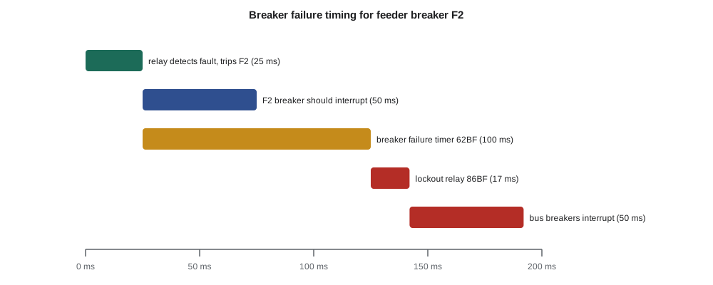
For feeder breaker F2, with a three-cycle breaker, a one-cycle reset of the fault detector and a two-cycle margin, the program sets the breaker failure timer at 100 ms. If F2 fails to interrupt, the fault is cleared in about 192 ms: relay detection, the timer, the lockout relay and the 25 kV main and other feeder breakers. That is much faster than remote backup, and it disconnects only the 25 kV bus rather than the whole station.
Breaker failure schemes deserve the same care as any protection that trips many breakers. A false breaker failure trip is as damaging as a bus fault. Good practice uses separate initiate and trip paths, checks the fault detector's sensitivity for low-current faults such as transformer turn faults, where the breaker may be asked to trip with little current, uses breaker auxiliary contacts for those cases, and retrips the failed breaker's second trip coil before tripping its neighbours.
Automatic reclosing
Most faults on overhead lines are temporary: lightning flashovers, conductor clashing in wind, and contacts with branches or animals that are burned clear by the fault. Automatic reclosing (79) recloses the breaker after a dead time, restoring service and, on transmission lines, restoring the network's strength quickly. Distribution reclosing practice was introduced in lesson 5. On transmission lines the main constraints are the time the fault arc's ionized path needs to de-ionize, so that the reclose does not restrike it, and stability.
The program evaluates a common rule of thumb for de-ionization time, 10.5 + kV/34.5 cycles: about 11 cycles at 25 kV, 14.5 cycles (242 ms) at 138 kV and 17 cycles at 230 kV. Larchmont recloses its 138 kV lines once, after a dead time of about 30 cycles, about half a second, from the end that is chosen as the leader, usually the end with the weaker source or the one where a reclose onto a permanent fault would do least harm. The other end follows only after the leader has reclosed successfully, confirmed by a synchronism check (25) that the voltages on both sides are close in magnitude, angle and frequency.
Reclosing is blocked in several situations: after breaker failure or bus protection operations, for faults on cables and transformers, after a trip by a time-delayed backup zone that suggests a fault outside the line, when a line crew has a hot-line hold, and on lines near large generators, where reclosing onto a permanent fault can apply severe torques to turbine-generator shafts. Some utilities use single-pole tripping and reclosing on extra-high-voltage lines, opening only the faulted phase for a single-line-to-ground fault, which keeps two phases transferring power during the dead time and greatly helps stability.
Worked problem
Can the breaker failure timer be shortened?
A stability study for the 138 kV breakers at Lincoln Road requires that a fault be cleared within 12 cycles (200 ms) even if a breaker fails. The relay takes 1.5 cycles, the breaker 3 cycles, the fault detector reset 1 cycle, the lockout relay 1 cycle and the backup breakers 3 cycles. What is the longest breaker failure timer that meets the requirement, and is the margin adequate?
Show solution
- Total clearing = relay + timer + lockout + backup breakers = 1.5 + T + 1 + 3 = 5.5 + T cycles.
- \[5.5 + T \le 12 \quad\Rightarrow\quad T \le 6.5\ \text{cycles}\]
- The timer must exceed breaker time plus reset: 3 + 1 = 4 cycles, leaving a margin of up to 2.5 cycles.
- A timer of 6 cycles gives a 2-cycle margin and clearing in 11.5 cycles, about 192 ms.
Answer: Up to 6.5 cycles; 6 cycles gives a 2-cycle margin and meets the 12-cycle limit.
Common mistakes
MistakeTreating bus protection like any other differential scheme.
InsteadCT saturation during external faults is the central problem; use high-impedance or saturation-aware low-impedance schemes.
MistakeSetting a high-impedance relay without checking CT knee points.
InsteadKnee points must be well above the setting, usually at least twice it.
MistakeSupervising breaker failure only with an overcurrent fault detector.
InsteadLow-current faults need breaker auxiliary contact supervision too.
MistakeReclosing both ends of a transmission line at once.
InsteadUse a leader and a follower with synchronism check.
Summary and key terms
- Bus faults are rare but severe; bus protection must be fast and especially secure.
- CT saturation during external faults is the main problem for bus differential schemes.
- High-impedance schemes are set above the voltage a fully saturated CT can produce.
- Low-impedance numerical schemes use restraint, saturation detection and dynamic zone selection.
- Breaker failure protection trips surrounding breakers if current persists after a trip and a timer.
- The breaker failure timer exceeds breaker time plus reset plus margin.
- Reclosing dead times allow de-ionization; synchronism checks and blocking rules keep reclosing safe.
- Bus differential
- Protection that sums the currents of all circuits connected to a bus.
- High-impedance differential
- A bus scheme with paralleled CTs and a high-impedance voltage-measuring relay.
- Breaker failure (50BF)
- Protection that trips adjacent breakers when a breaker fails to clear a fault.
- Lockout relay (86)
- A hand-reset relay that trips and blocks closing of several breakers.
- De-ionization time
- The time an arc path needs to recover its insulation before reclosing.
- Synchronism check (25)
- A function that permits closing only when voltages on both sides are matched.
- Single-pole tripping
- Opening only the faulted phase of a line for a line-to-ground fault.
Practice problems
Work each problem on paper first, then reveal the answer to check.
External fault 6000 A, CT ratio 120, R_CT 0.4 Ω, leads 0.6 Ω. What voltage would a saturated CT produce?
Show answer
50 A × 1.0 Ω = 50 V.
What safety factor is commonly applied to that voltage?
Show answer
About 1.5 to 2.
Why does breaker failure trip through a lockout relay?
Show answer
To trip all adjacent breakers and block reclosing until someone investigates.
Breaker 3 cycles, reset 1 cycle, margin 2 cycles. What is the breaker failure timer?
Show answer
6 cycles, 100 ms.
Estimate the de-ionization time for a 138 kV line.
Show answer
About 14.5 cycles, roughly 240 ms.
Why is reclosing blocked after a bus protection operation?
Show answer
Bus faults are likely permanent and reclosing into them causes severe damage.
Lesson quiz · 5 questions
Score 60% or more to complete this lesson.
Create a free account to save your progress, take quizzes and earn a certificate.