
ELE-480 · Lesson 1 of 12 · 24 min
Protection principles and zones of protection
Leo Tremblay has spent three co-op terms at Cedarline Controls designing the electronics of traffic-signal equipment. For his last term before graduation he has moved across the city to Larchmont Energy, an invented regional utility that owns the 138 kV lines and 25 kV distribution feeders around Fredericton, New Brunswick. He joins the protection and control group, led by Nadine Cormier, P.Eng., a protection engineer with twenty years of relay settings behind her, and Ravi Bhatt, the senior protection technologist who tests every relay before it goes into service. Their current project is a full protection review of the Lincoln Road substation, and Leo will follow it from the first fault study to the final settings. This course follows that review.
Lincoln Road is an ordinary suburban substation, which is exactly why it is a good teacher. Two 138 kV lines enter it, one from the Hollis station 40 km away and one from Grafton. A 25 MVA transformer, T1, steps the voltage down to a 25 kV bus (24.94 kV phase to phase, 14.4 kV phase to ground), which feeds four distribution feeders. Feeder F1 serves a water utility's pumping station with a large induction motor. Feeder F2 is a long suburban and rural feeder with a line recloser and fused laterals. Feeder F3 now carries a 9.9 MW solar plant. Feeder F4 connects a small hydroelectric station, Larchmont Falls, with two 5 MVA generators. Almost every protection problem a distribution and subtransmission engineer meets appears somewhere in this one station.
What protection is for
A power system is built to carry energy safely from generators to loads, and almost all of the time it does. But insulation fails, lightning strikes lines, trees fall, animals climb into switchgear, cables are dug up and equipment wears out. Each of these can create a fault: an unintended path for current, usually between a phase and ground or between phases. Fault currents are large, often ten to twenty times normal load current, and the energy released at the fault and in the equipment carrying the current grows with the square of the current and with the time it flows. A fault left in place damages conductors and transformers, threatens people nearby, depresses voltage for every customer in the area and can make generators lose synchronism.
Protection is the set of devices that detect abnormal conditions and remove the faulted part of the system, quickly and with as little disruption as possible to the rest. A protection system has several parts that must all work. Instrument transformers, current transformers (CTs) and voltage transformers (VTs), reduce primary currents and voltages to safe, standard secondary values. Relays measure those signals and decide whether to trip. Communication channels carry signals between relays at different stations. A station battery supplies the trip circuit and the relays, so that protection works even when the fault has collapsed the AC voltage. Circuit breakers interrupt the current. If any one of these fails, the protection fails, which is why engineers speak of the protection system rather than of the relay alone.
Protection is not designed to prevent faults; that is the job of insulation design, lightning protection, vegetation management and good maintenance. Its job is to limit the consequences of the faults that happen anyway. A well-protected system still has faults, but they last a few cycles instead of seconds, they interrupt a few customers instead of thousands, and they rarely destroy equipment or hurt anyone.
Five qualities of good protection
Protection engineers judge a scheme against a short list of qualities that pull in different directions. Reliability has two halves. Dependability is the certainty that the protection will operate for faults it is meant to clear. Security is the certainty that it will not operate when it should not, for faults outside its zone, for load, for power swings or for transformer inrush. Selectivity, also called discrimination, means that only the breakers nearest the fault open, so the smallest possible part of the system is disconnected. Speed means clearing the fault quickly to limit damage, preserve stability and reduce the hazard to people. Simplicity and economy round out the list: a scheme that is easy to understand, set and test is less likely to be set wrongly, and the cost of protection must be in proportion to the value of what it protects.
| Quality | Question it answers | What happens when it is missing |
|---|---|---|
| Dependability | Will it trip for every fault in its zone? | A fault persists until backup operates, with more damage and a wider outage |
| Security | Will it stay quiet for everything else? | Healthy equipment is switched off; customers lose supply for no reason |
| Selectivity | Does only the nearest breaker open? | A whole substation or feeder trips for a fault on one lateral |
| Speed | How long does the fault last? | Equipment damage, arc flash energy and stability risk all grow |
| Simplicity and economy | Can it be set, tested and afforded? | Settings errors and untested logic cause misoperations |
The tension between dependability and security is the oldest in the field. Adding a second relay in parallel, so that either can trip, makes a failure to trip much less likely but doubles the chance of a false trip. Requiring two of three relays to agree improves both, at the cost of a third relay and more wiring. The code below puts numbers on that trade-off with illustrative probabilities and then works out a typical clearing-time budget.
# Dependability and security of three relay arrangements (illustrative per-fault probabilities)
pf = 0.01    # probability that one relay fails to trip for an in-zone fault
pm = 0.002   # probability that one relay trips falsely for an out-of-zone fault
schemes = {
    'one relay':                      (pf, pm),
    'two relays, either trips (1oo2)': (pf**2, 1 - (1 - pm)**2),
    'three relays, two must agree (2oo3)': (3*pf**2*(1 - pf) + pf**3, 3*pm**2*(1 - pm) + pm**3),
}
print("scheme                                fail to trip    false trip")
for name, (a, b) in schemes.items():
    print(f"{name:38s} {a:10.6f}     {b:10.6f}")

# Fault clearing time budget at 60 Hz
cyc = 1000/60
relay, breaker = 1.5, 3.0          # cycles
t = (relay + breaker)*cyc
print(f"\nrelay {relay} cycles + breaker {breaker} cycles = {t:.0f} ms")
# Arc energy grows with clearing time: compare 75 ms with a 0.5 s time-delayed backup
for tc in (t/1000, 0.5):
print(f"clearing in {tc*1000:5.0f} ms: relative fault energy {tc/(t/1000):5.1f} x")scheme fail to trip false trip one relay 0.010000 0.002000 two relays, either trips (1oo2) 0.000100 0.003996 three relays, two must agree (2oo3) 0.000298 0.000012 relay 1.5 cycles + breaker 3.0 cycles = 75 ms clearing in 75 ms: relative fault energy 1.0 x clearing in 500 ms: relative fault energy 6.7 x
With a 1 % chance that one relay fails to trip and a 0.2 % chance that it trips falsely, two relays in parallel cut the failure-to-trip probability a hundredfold but almost double the false-trip probability. Two-out-of-three voting gives a failure-to-trip probability of about 0.03 % and a false-trip probability of about 0.001 %, better on both counts. That is why the most critical transmission elements often use redundant or voting schemes, while a distribution feeder makes do with one relay and relies on the next device upstream as backup.
Zones of protection
The system is divided into zones, each covering one element: a line, a transformer, a bus, a generator, a motor or a feeder. Each zone has its own protection, which trips the breakers that isolate that element. The boundaries of a zone are set by the location of the CTs that feed its relays, and they are arranged so that adjacent zones overlap around each breaker. The overlap ensures that a fault anywhere, including in the breaker itself, lies inside at least one zone. The price of the overlap is that a fault in the small region between two sets of CTs trips both zones, a few more breakers than strictly necessary, which is far better than leaving a gap.
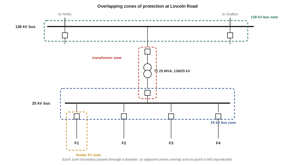
At Lincoln Road, Nadine shows Leo how each zone is defined. The 138 kV bus zone uses CTs on the line side of each line breaker and on the high-voltage side of T1's breaker. The transformer zone uses CTs on the bus side of the 138 kV transformer breaker and on the bus side of the 25 kV main breaker, so it includes both breakers. The 25 kV bus zone uses CTs on the transformer side of the main breaker and on the line side of each feeder breaker. Each feeder zone starts at its breaker's CTs and extends to the end of the feeder, where it is covered further by the recloser and fuses.
Primary and backup protection
Every zone has primary protection, which is expected to clear faults in that zone quickly and selectively. Because any part of a protection system can fail, every fault must also be cleared by backup protection if the primary fails. Local backup duplicates relays, CT cores, trip coils or batteries at the same station; a breaker failure scheme, covered in lesson 11, trips the surrounding breakers if the primary breaker does not interrupt. Remote backup is provided by protection at other stations, which sees the fault as being further away and trips after a delay. Remote backup is cheap and independent of the local station, but it is slow and disconnects more of the system. A feeder relay at Lincoln Road is remote backup for the recloser on that feeder, and the transformer's overcurrent relays are backup for the feeder relays.
Backup must coordinate with primary protection: it waits long enough for the primary to act. The margin between them, the coordination time interval, is typically 0.2 to 0.4 s for electromechanical relays and as little as 0.2 s for modern numerical relays with fast breakers. Lessons 4 and 5 develop coordination in detail.
Clearing time
A fault is cleared when the breaker interrupts the current, which happens at a current zero after the contacts have separated far enough for the arc not to restrike. The total clearing time is the relay's operating time plus the breaker's interrupting time. A numerical relay with an instantaneous element might operate in one to one and a half cycles, and a modern transmission breaker interrupts in two to three cycles; at 60 Hz one cycle is about 16.7 ms. The program's budget of 1.5 cycles for the relay and 3 cycles for the breaker gives 75 ms. A time-delayed backup that clears in 0.5 s lets about 6.7 times as much fault energy into the arc and the equipment.
Speed matters most on transmission systems, where a slow fault clearance can make generators lose synchronism and spread the disturbance far beyond the fault. The longest clearing time a system can tolerate before stability is lost, the critical clearing time from ELE-380, sets an upper bound on the clearing time of transmission protection. On distribution systems the main concerns are equipment damage, conductor burndown, arc flash hazard to workers and the voltage dip seen by other customers.
Relay technologies and device numbers
Protection relays have gone through three generations. Electromechanical relays, built from induction discs and balanced beams, dominated until the 1980s and many are still in service. Static relays replaced moving parts with analog electronics. Today almost all new relays are numerical: they sample the CT and VT signals, filter them digitally to extract the fundamental phasors, and run protection algorithms in a microprocessor. A single numerical relay can provide dozens of functions, record faults, communicate with other relays and with the control centre, and supervise itself, raising an alarm if it detects an internal failure.
Protection functions are identified by standard device function numbers defined in IEEE C37.2, used throughout North America on drawings and in relay manuals. A few appear in nearly every lesson of this course.
| Number | Function |
|---|---|
| 21 | Distance relay |
| 25 | Synchronism check |
| 27 / 59 | Undervoltage / overvoltage |
| 32 | Directional power |
| 40 | Loss of field |
| 46 | Negative-sequence (current unbalance) |
| 49 | Thermal |
| 50 / 51 | Instantaneous / time overcurrent |
| 50BF | Breaker failure |
| 63 | Pressure (sudden pressure relay) |
| 67 | Directional overcurrent |
| 79 | Reclosing |
| 81 | Frequency |
| 85 | Communication-aided (pilot) scheme |
| 86 | Lockout relay |
| 87 | Differential |
Larchmont's practices sit inside a framework of standards and rules. The CSA standards for instrument transformers and the Canadian Electrical Code govern equipment and installations, and Larchmont follows IEEE protection guides, which Canadian utilities use widely. As a transmission owner in an interconnected system, it must also meet the reliability standards of the North American Electric Reliability Corporation (NERC), which provincial authorities make enforceable in Canada; several of them, such as those on protection system maintenance and relay loadability, apply directly to protection engineers. Settings are prepared and sealed by a licensed professional engineer under the provincial engineering act.
Before Leo touches a relay setting, Ravi gives him the rule that every protection group lives by: the relay settings in service must match the approved settings exactly, and every change goes through review, testing and documentation. Most protection misoperations in North America are caused not by failed hardware but by incorrect settings, logic or design, and a careful change process is the best defence.
Worked problem
Which breakers open, and which protection is backup?
A tree falls across feeder F2 four kilometres from Lincoln Road, upstream of the recloser on the feeder. Which protection should clear the fault, what is its backup, and what is the backup's backup?
Show solution
- The fault lies inside the F2 feeder zone and upstream of the recloser, so the recloser sees no fault current and stays closed.
- Primary protection is the F2 feeder relay, which trips the F2 breaker.
- If the F2 relay or breaker fails, the breaker failure scheme trips the 25 kV main breaker and the other feeders (local backup), and the transformer's 25 kV overcurrent relay is the remote backup after a coordination delay.
- If all of those failed, the 138 kV line relays at Hollis and Grafton would eventually see the fault through T1 in their remote zones, though they may not see it at all for a fault this far down the feeder, which is why the local backups matter.
Answer: The F2 relay is primary; breaker failure and the transformer's overcurrent relay are backup.
Common mistakes
MistakeCalling the relay alone 'the protection'.
InsteadCTs, VTs, wiring, the battery, the channel and the breaker must all work; the protection system fails if any one does.
MistakeLeaving gaps between zones to avoid tripping extra breakers.
InsteadZones always overlap at breakers; tripping a few extra breakers is better than leaving a fault uncleared.
MistakeMaking protection as sensitive and fast as possible everywhere.
InsteadSensitivity and speed must be balanced against security and selectivity; an over-sensitive relay trips for load and inrush.
MistakeTreating backup as a nice-to-have.
InsteadEvery fault must be cleared even if one element of the primary protection fails.
Summary and key terms
- Protection detects faults and abnormal conditions and isolates the smallest possible part of the system.
- A protection system includes instrument transformers, relays, channels, the station battery and breakers.
- Dependability, security, selectivity, speed and simplicity must be balanced against one another.
- Zones of protection are bounded by CTs and overlap around every breaker.
- Each zone has primary protection and local or remote backup that coordinates with it.
- Clearing time equals relay time plus breaker time; at 60 Hz a cycle is about 16.7 ms.
- IEEE C37.2 device numbers identify functions; settings must be controlled and documented carefully.
- Fault
- An unintended path for current between phases or between a phase and ground.
- Dependability
- The certainty that protection operates for faults in its zone.
- Security
- The certainty that protection does not operate when it should not.
- Selectivity
- Tripping only the breakers needed to isolate the fault.
- Zone of protection
- The part of the system covered by one protection scheme, bounded by its CTs.
- Backup protection
- Protection that clears a fault if the primary protection fails, usually after a delay.
- Clearing time
- The time from fault inception to interruption of the current: relay time plus breaker time.
- Numerical relay
- A microprocessor relay that samples and digitally processes CT and VT signals.
Practice problems
Work each problem on paper first, then reveal the answer to check.
Name the two halves of protection reliability.
Show answer
Dependability and security.
Why do zones of protection overlap at breakers?
Show answer
So that no part of the system, including the breaker, is left outside every zone.
A relay operates in 1 cycle and the breaker in 2 cycles. What is the clearing time at 60 Hz?
Show answer
3 cycles, or 50 ms.
What is the difference between local and remote backup?
Show answer
Local backup is at the same station (duplicate relays, breaker failure); remote backup is protection at another station that trips after a delay.
What does device number 87 denote?
Show answer
Differential protection.
Two relays in parallel, either able to trip: does this improve dependability or security?
Show answer
Dependability, at the cost of security.
Lesson quiz · 5 questions
Score 60% or more to complete this lesson.
Create a free account to save your progress, take quizzes and earn a certificate.