
ELE-455 · Lesson 8 of 12 · 22 min
Antennas for products
ELE-360 designed the TLR-1 antennas from first principles: a quarter-wave monopole on the pole housing and a 6 dBi panel on the cabinet mast. Both were essentially textbook antennas with room to be themselves. TLR-2 is harder. The pole unit now needs a BLE antenna as well as the telemetry antenna, inside the same small housing, and the city wants the pole unit's external whip removed because it is damaged by vandals and snowplow spray. The cabinet unit needs a cellular antenna that covers bands from about 700 MHz to 2.2 GHz. These are product antennas: small, close to circuit boards, metal and people, and judged not by their gain in an ideal setting but by how much power they actually radiate, and how well they actually receive, inside the finished product.
Why small antennas are hard
An antenna radiates efficiently when its size is comparable to a wavelength. The TLR-1 monopole, 78 mm long at 915 MHz, is a quarter wavelength. Shrinking an antenna below that size does not stop it radiating, but it stores much more energy in its near field relative to the energy it radiates. Its radiation resistance falls, its reactance grows, its bandwidth narrows and its efficiency drops as conductor and dielectric losses become comparable to the small radiation resistance. ELE-360 found that a 2 cm monopole at 915 MHz has a radiation resistance of only 1.47 Ω and would be about 60 % efficient with just 1 Ω of loss.
Chu's limit makes this precise. An antenna that fits inside a sphere of radius a has a minimum possible radiation Q, which depends only on ka, where k = 2π/λ.
Since bandwidth is roughly inversely proportional to Q, an antenna that is electrically small cannot be both small and broadband, no matter how clever its shape or its matching network. The Bode–Fano limit of lesson 3 then bounds what any matching network can add.
import math
c = 299792458.0

# 1. Rectangular microstrip patch for 2.44 GHz on 1.6 mm FR-4 (er 4.4)
f, er, h = 2.44e9, 4.4, 1.6e-3
W = c/(2*f)*math.sqrt(2/(er + 1))
ee = (er + 1)/2 + (er - 1)/2/math.sqrt(1 + 12*h/W)
dL = 0.412*h*(ee + 0.3)*(W/h + 0.264)/((ee - 0.258)*(W/h + 0.8))
Lp = c/(2*f*math.sqrt(ee)) - 2*dL
print(f"patch: W {W*1e3:.1f} mm, L {Lp*1e3:.1f} mm, eps_eff {ee:.2f}  (free-space half wave {c/(2*f)*1e3:.1f} mm)")

# 2. Chu limit: minimum radiation Q of an antenna that fits in a sphere of radius a
for name, fr, a in (("BLE chip antenna", 2.44e9, 0.006), ("sub-GHz PIFA in pole housing", 915e6, 0.030), ("same size at 710 MHz (LTE band 12)", 710e6, 0.030)):
    ka = 2*math.pi*fr/c*a
    q = 1/ka**3 + 1/ka
    print(f"{name:30s} ka {ka:.3f}  Q_min {q:6.1f}  best VSWR-2 bandwidth about {100*(1/q)*(1/math.sqrt(2)):.1f} %")

# 3. Radiated budget: total radiated power and total isotropic sensitivity
def mismatch_db(vswr): g = (vswr - 1)/(vswr + 1); return -10*math.log10(1 - g*g)
cases = [("pole, sub-GHz, free space", 14.0, 1.5, -2.5, -113.0),
         ("pole, sub-GHz, hand on housing", 14.0, 3.0, -6.5, -113.0),
         ("cabinet LTE-M, roof antenna, 6 m cable", 23.0, 1.8, -1.0 - 2.4, -101.0)]
for name, pc, vswr, eff_db, sens in cases:
    ml = mismatch_db(vswr)
    trp = pc - ml + eff_db
    tis = sens + ml - eff_db
    print(f"{name:38s} mismatch {ml:4.2f} dB  TRP {trp:5.1f} dBm  TIS {tis:6.1f} dBm")

# 4. Isolation between two antennas on the cabinet roof (free-space Friis estimate at the higher-loss frequency)
for d in (0.10, 0.25, 0.50):
    lam = c/915e6
    iso = 20*math.log10(4*math.pi*d/lam)        # with 0 dBi gains towards each other
print(f"antennas {d*100:.0f} cm apart at 915 MHz: about {iso:4.1f} dB coupling loss (far-field estimate)")patch: W 37.4 mm, L 28.9 mm, eps_eff 4.08 (free-space half wave 61.4 mm) BLE chip antenna ka 0.307 Q_min 37.9 best VSWR-2 bandwidth about 1.9 % sub-GHz PIFA in pole housing ka 0.575 Q_min 7.0 best VSWR-2 bandwidth about 10.1 % same size at 710 MHz (LTE band 12) ka 0.446 Q_min 13.5 best VSWR-2 bandwidth about 5.2 % pole, sub-GHz, free space mismatch 0.18 dB TRP 11.3 dBm TIS -110.3 dBm pole, sub-GHz, hand on housing mismatch 1.25 dB TRP 6.3 dBm TIS -105.3 dBm cabinet LTE-M, roof antenna, 6 m cable mismatch 0.37 dB TRP 19.2 dBm TIS -97.2 dBm antennas 10 cm apart at 915 MHz: about 11.7 dB coupling loss (far-field estimate) antennas 25 cm apart at 915 MHz: about 19.6 dB coupling loss (far-field estimate) antennas 50 cm apart at 915 MHz: about 25.7 dB coupling loss (far-field estimate)
The program applies the limit to three cases. A BLE chip antenna that fits in a 6 mm sphere at 2.44 GHz has ka = 0.31, Q_min = 38 and a best possible 2:1 VSWR bandwidth of about 1.9 %, smaller than the 3.4 % needed for the 2400–2483.5 MHz band. Chip antennas work in practice because they are not radiating alone: they excite currents on the circuit board's ground plane, and the board, tens of millimetres long, is the real radiator. That is why a chip antenna's data sheet always specifies the ground plane size and the keep-out area around it. A sub-GHz antenna filling a 30 mm sphere in the pole housing has Q_min = 7 and up to about 10 % bandwidth, comfortably more than the 2.8 % of 902–928 MHz. The same size at 710 MHz, LTE band 12, has Q_min = 13.5 and only 5 % bandwidth for one band, with no hope of covering 700 MHz to 2.2 GHz. That calculation is why Amara decides early that the cellular antenna will be an external roof-mounted antenna on the cabinet, not a part on the board.
Antenna types for products
The inverted-F antenna and its planar form, the planar inverted-F antenna (PIFA), are the workhorses of compact devices. A PIFA is a quarter-wave monopole folded over a ground plane: a radiating plate or trace parallel to the board, shorted to ground at one end and fed a short distance from the short. The position of the feed relative to the short sets the input impedance, so a PIFA can be matched to 50 Ω without a separate network. Its bandwidth grows with its height above the ground plane. A printed inverted-F, etched on the board itself, costs nothing and is the usual BLE antenna in phones and sensors.
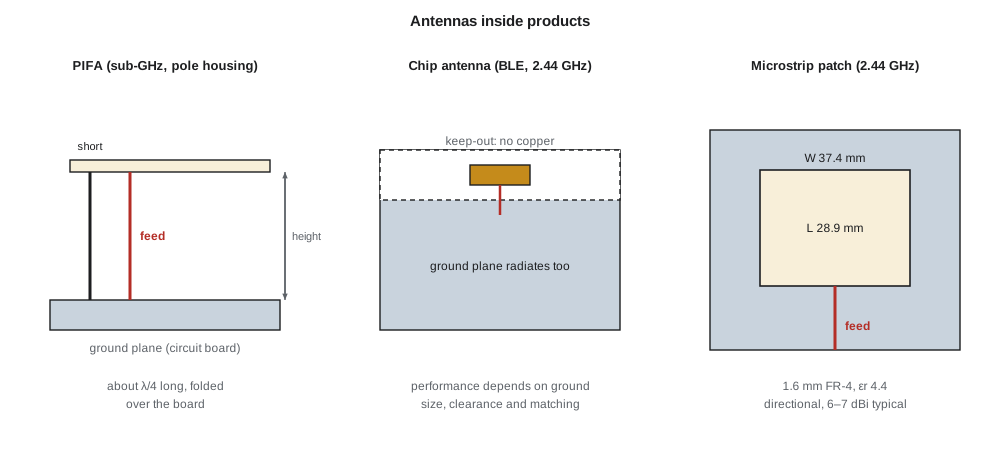
Ceramic chip antennas are small blocks of high-permittivity ceramic with a printed conductor. Their high permittivity shortens the conductor electrically, but as the Chu limit shows, the ground plane does much of the radiating, and their performance depends heavily on where they sit on the board. They save area at the price of efficiency and bandwidth, and they need a matching network tuned on the actual board.
The microstrip patch is a resonant rectangle of copper over a ground plane, about half a guided wavelength long. It radiates from its two open edges, has a broadside directional pattern with a gain of 6 to 7 dBi, and a narrow bandwidth that grows with substrate thickness. The program's design equations give a patch 37.4 mm wide and 28.9 mm long for 2.44 GHz on 1.6 mm FR-4. A patch would suit a directional BLE link from a cabinet to a technician standing across the street, but for TLR-2's maintenance link, which must work in any direction, Priya uses a printed inverted-F.
The pole unit antennas
For the telemetry antenna inside the pole housing, Priya designs a PIFA from a stamped brass plate 8 mm above the board, about 60 mm long, folded to fit beneath the polycarbonate cap that ELE-360 already characterized. The board's 60 × 40 mm ground plane is shorter than a quarter wavelength at 915 MHz, so the PIFA and the board together form the radiator, and the pole's metal housing, a few centimetres below, couples to both. The antenna's measured efficiency in free space is about −2.5 dB (56 %), lower than the external whip's 90 %, and its pattern is less uniform, but it cannot be broken off.
The BLE antenna is a printed inverted-F at the opposite corner of the board, oriented at right angles to the PIFA so that the two antennas' fields are partly cross-polarized. The board's layout follows the module maker's rules: no copper, components or traces within the keep-out area, and the antenna at the board edge with the housing's plastic cap above it, not metal.
Efficiency, mismatch and the user
Two numbers matter for a product antenna: how much of the power delivered to it is radiated (radiation efficiency) and how much of the power available from the radio reaches it (mismatch). Total efficiency combines them, and the product's real performance is the radio's conducted power or sensitivity adjusted by total efficiency. Over-the-air test standards express this as total radiated power (TRP), the power radiated in all directions combined, and total isotropic sensitivity (TIS), the received power level, averaged over all directions, at which the receiver just meets its error-rate requirement.
The program shows the pole unit's telemetry radio in two situations. In free space, with a VSWR of 1.5, the mismatch loss is 0.18 dB and with −2.5 dB efficiency the TRP is 11.3 dBm from 14 dBm conducted, and the TIS is −110.3 dBm. With a technician's hand wrapped around the housing, as happens during maintenance, the antenna detunes to a VSWR of 3 and absorbs power in the hand, the efficiency falls to −6.5 dB, the TRP to 6.3 dBm and the TIS to −105.3 dBm. That 5 dB loss is acceptable for a pole that is only being serviced, because the link margin calculated in ELE-350 was 38 dB, but it is the reason Daniel's ELE-360 action item, measuring the pattern on a real pole with a hand on the housing, was worth doing.
Detuning is the main enemy of small antennas. Metal nearby, the housing, a hand, a nearby cable or even the plastic cap shift the resonance and change the impedance. Designers tune antennas in their final housings, never on bare boards, and leave a matching network with unpopulated pads so that the match can be adjusted on the production design. Some products go further and use tunable matching networks or switched antenna elements under software control; TLR-2 does not need that.
The cabinet's cellular antenna
For the cellular link, Amara chooses an external low-profile antenna mounted on the cabinet roof, covering 698–960 MHz and 1710–2200 MHz, with a peak gain of about 3 dBi in the low bands. A low-loss cable 6 m long brings it to the module inside the cabinet, with 2.4 dB of loss at 739 MHz. Modules that support two receive antennas, a requirement in some LTE categories but optional for LTE-M, would need a second antenna separated from the first for diversity; the chosen module uses one. The program shows that the cable loss reduces the cabinet's TRP from 23 dBm conducted to about 19 dBm and degrades its TIS by a similar amount. Mounting the antenna on the roof rather than inside the steel cabinet is worth far more than the cable costs: a steel cabinet would attenuate the signal by 20 dB or more, as ELE-360's shielding calculations showed.
Isolation between antennas
Three antennas on one product couple to each other. The coupling between two antennas is measured as |S₂₁| between their ports and quoted as isolation in decibels. A rough far-field estimate for two antennas a distance d apart, each with 0 dBi gain toward the other, is the free-space path loss 20 log₁₀(4πd/λ); the program gives about 12 dB at 10 cm, 20 dB at 25 cm and 26 dB at 50 cm at 915 MHz. Real isolation can be better, with cross-polarization and pattern nulls, or worse, when the antennas share a ground plane whose currents couple them. On the cabinet roof, the LTE-M and telemetry antennas both operate below 1 GHz, and their isolation is a key number for lesson 11.
Over-the-air measurement
Leo cannot measure TRP and TIS on the bench. They are measured in an anechoic chamber whose walls absorb radio waves: the product sits on a positioner that rotates it through all angles while a measurement antenna samples the field, and software integrates the results. Cellular carriers specify TRP and TIS limits for devices on their networks, and the over-the-air test plans published by the CTIA (an industry association) are widely used for those measurements; lesson 10 returns to carrier approval. For the telemetry and BLE antennas, Cedarline rents time in a chamber at a test laboratory and measures the pole unit in its housing on a short section of real pole.
Worked problem
From conducted power to TRP
A radio delivers 8 dBm conducted to an antenna with VSWR 2.0 and radiation efficiency 40 %. Find the mismatch loss, total efficiency and TRP.
Show solution
- \[|\Gamma| = \frac{2 - 1}{2 + 1} = 0.333, \quad L_{mm} = -10\log_{10}(1 - 0.111) = 0.51\ \text{dB}\]
- \[\eta_{rad} = 10\log_{10}(0.40) = -3.98\ \text{dB}\]
- \[\mathrm{TRP} = 8 - 0.51 - 3.98 = 3.5\ \text{dBm}\]
Answer: Mismatch loss 0.5 dB, total efficiency −4.5 dB (36 %), TRP 3.5 dBm.
Common mistakes
MistakeChoosing an antenna by its data-sheet gain.
InsteadProduct performance depends on efficiency in the housing; TRP and TIS measured over the air are the true figures.
MistakeTuning an antenna on a bare board.
InsteadHousings, nearby metal and users detune antennas; tune in the final housing and leave matching pads.
MistakeExpecting a chip antenna to work independently of the board.
InsteadThe ground plane is part of the radiator; follow the data sheet's ground size and keep-out rules.
MistakePutting a cellular antenna inside a steel cabinet to protect it.
InsteadThe enclosure attenuates the signal far more than a cable to a roof antenna.
Summary and key terms
- Electrically small antennas have low radiation resistance, narrow bandwidth and lower efficiency; Chu's limit gives Q_min = 1/(ka)³ + 1/(ka).
- PIFAs and printed inverted-F antennas are compact and self-matching; chip antennas rely on the ground plane; patches are directional.
- Total efficiency combines radiation efficiency and mismatch; TRP and TIS describe real radiated performance.
- Hands, housings and nearby metal detune antennas; tuning is done in the final product.
- The TLR-2 cabinet uses an external multiband roof antenna for LTE-M because no small board antenna can cover 700 MHz to 2.2 GHz efficiently.
- Antenna-to-antenna isolation can be estimated from free-space loss and must be measured in the product.
- Electrically small antenna
- An antenna much smaller than a wavelength, usually with ka well below 1.
- Chu limit
- The minimum radiation Q of an antenna that fits within a given sphere.
- PIFA
- A planar inverted-F antenna, a folded quarter-wave radiator over a ground plane.
- Radiation efficiency
- The fraction of accepted power that an antenna radiates.
- Total radiated power (TRP)
- The power radiated by a device in all directions combined.
- Total isotropic sensitivity (TIS)
- A receiver's sensitivity averaged over all directions, including antenna effects.
- Detuning
- A shift in an antenna's resonance caused by its surroundings.
- Antenna isolation
- The coupling loss between the ports of two antennas.
Practice problems
Work each problem on paper first, then reveal the answer to check.
What is ka for a 20 mm-radius sphere at 2.44 GHz?
Show answer
k = 51.1 rad/m; ka ≈ 1.02.
Find Q_min for ka = 0.5.
Show answer
8 + 2 = 10.
A radio's sensitivity is −100 dBm conducted; the antenna has 0.3 dB mismatch loss and −3 dB efficiency. What is the TIS?
Show answer
−100 + 0.3 + 3 = −96.7 dBm.
Why is a PIFA easy to match to 50 Ω?
Show answer
Moving the feed relative to the shorting pin changes its input impedance.
Estimate the free-space coupling loss between antennas 1 m apart at 900 MHz.
Show answer
20 log₁₀(4π × 1/0.333) ≈ 31.5 dB.
Why does a chip antenna data sheet specify a ground plane size?
Show answer
The ground plane carries much of the radiating current, so it sets the antenna's resonance and efficiency.
Lesson quiz · 5 questions
Score 60% or more to complete this lesson.
Create a free account to save your progress, take quizzes and earn a certificate.