
ELE-455 · Lesson 12 of 12 · 25 min
TLR-2 RF design and compliance plan
In June, Daniel Fortin calls the TLR-2 design review. On the table are the second-revision boards, Leo's measurement records, Priya's simulations and Amara's compliance plan. Daniel's question is the one every design review asks: is this design ready to be built in volume and submitted for certification, and if not, what is missing? This capstone lesson walks through the review as the team presents it: the final architecture, the link budgets for all three radios, the transmitter's emissions, the coexistence results, the antenna placement, the certification plan and the test plan. It ties together every lesson of the course, and ends with the open items Daniel records before he signs. Daniel signs as a professional engineer, and Cedarline's quality system in Fredericton records his review.
The final architecture
Amara opens with the block diagram of lesson 1, now annotated with measured values. The cabinet's telemetry receiver is line-up C: a SAW filter with 1.5 dB loss, the discrete LNA of lesson 5 with 14.7 dB gain and 0.9 dB noise figure, and the low-IF transceiver, giving a measured sensitivity of −113 dBm at a 10⁻³ packet error rate. The transmit path runs from the transceiver through the class AB power amplifier of lesson 6 at 27 dBm, the Pi match of lesson 3, the Chebyshev filter of lesson 4 with its 1830 MHz trap, and a directional coupler, to a transmit/receive switch. The synthesizer uses a 30 MHz reference after the clock changes of lesson 11. The pole unit is the same without the PA and LNA, transmitting 14 dBm from the transceiver and receiving through a ceramic filter, with the PIFA of lesson 8. The cellular module and BLE system-on-chip are certified parts, connected and laid out as their makers' guides require, now with the antenna connection on the correct side of the duplexer.
Link budgets
Priya presents the budgets for every link in one program, each compared with a required margin: 20 dB for the telemetry links, carried over from ELE-350's analysis of Rayleigh fading and bus shadowing; 10.3 dB for the cellular link, the 90 % location-reliability margin of lesson 9; and 10 dB for the BLE maintenance link.
import math

def hata(f, d, hb, hm):
    a = (1.1*math.log10(f) - 0.7)*hm - (1.56*math.log10(f) - 0.8)
    return 69.55 + 26.16*math.log10(f) - 13.82*math.log10(hb) - a + (44.9 - 6.55*math.log10(hb))*math.log10(d)
def fspl(f, d): return 32.45 + 20*math.log10(f) + 20*math.log10(d)

links = []
# name, tx power, tx losses, tx gain, path loss, other losses, rx gain, rx losses, sensitivity, required margin
links.append(("Pole -> cabinet, 915 MHz, 45 m", 14.0, 0.5, 2.0, fspl(915, 0.045), 15.0 + 3.0, 6.0, 2.0, -113.0, 20.0))
links.append(("Cabinet -> cabinet, 915 MHz, 600 m", 27.0, 2.0, 6.0, 89.9 + 6.0, 10.2, 6.0, 2.0, -113.0, 20.0))
links.append(("Cabinet -> cell site, LTE-M 739 MHz, 3 km", 23.0, 2.4, 3.0, hata(739, 3.0, 30, 6), 6.0, 15.0, 2.0, -126.0, 10.3))
links.append(("Cabinet -> cell site, LTE-M 739 MHz, 6 km", 23.0, 2.4, 3.0, hata(739, 6.0, 30, 6), 6.0, 15.0, 2.0, -126.0, 10.3))
links.append(("Phone -> pole, BLE 2.44 GHz, 10 m", 0.0, 0.0, -3.0, fspl(2440, 0.010), 10.0, 0.0, 1.0, -94.0, 10.0))
for (name, pt, lt, gt, pl, lo, gr, lr, sens, need) in links:
    pr = pt - lt + gt - pl - lo + gr - lr
    m = pr - sens
    print(f"{name:42s} path {pl:6.1f} dB  received {pr:7.1f} dBm  margin {m:5.1f} dB  {'meets' if m >= need else 'SHORT of'} the {need:.1f} dB target")

# Duty cycle of the cabinet's 27 dBm sub-GHz transmitter in a 20 s window (hop dwell rule 0.4 s)
tx_per_s, t_pkt = 1.6, 5.12e-3
per_chan = tx_per_s*20*t_pkt/50
print(f"average occupancy per channel in 20 s: {per_chan*1e3:.1f} ms (limit 400 ms)")Pole -> cabinet, 915 MHz, 45 m path 64.7 dB received -63.2 dBm margin 49.8 dB meets the 20.0 dB target Cabinet -> cabinet, 915 MHz, 600 m path 95.9 dB received -71.1 dBm margin 41.9 dB meets the 20.0 dB target Cabinet -> cell site, LTE-M 739 MHz, 3 km path 129.9 dB received -99.3 dBm margin 26.7 dB meets the 10.3 dB target Cabinet -> cell site, LTE-M 739 MHz, 6 km path 140.5 dB received -109.9 dBm margin 16.1 dB meets the 10.3 dB target Phone -> pole, BLE 2.44 GHz, 10 m path 60.2 dB received -74.2 dBm margin 19.8 dB meets the 10.0 dB target average occupancy per channel in 20 s: 3.3 ms (limit 400 ms)
The pole-to-cabinet link, with 14 dBm, 2 dBi at the pole, the 6 dBi cabinet panel, 15 dB of bus shadowing and 3 dB of urban noise, has 49.8 dB of margin, about 11 dB more than TLR-1's 38.3 dB, mostly from the cabinet's better receiver and its panel antenna. The cabinet-to-cabinet link over 600 m, with the path loss from ELE-350's two-ray model, a 6 dB Fresnel-zone allowance and a shadowing margin, has 41.9 dB at 27 dBm, enough that the power control of lesson 6 will usually turn the transmitter down. The cellular link to a cell site 3 km away, using Hata at 739 MHz with the antenna on a mast arm, has 26.7 dB of margin, and 16.1 dB at 6 km. The BLE link from a phone held 10 m from a pole, with a 10 dB allowance for the technician's body and the housing, has 19.8 dB.
| Link | Margin | Required | Comment |
|---|---|---|---|
| Pole to cabinet, 915 MHz, 45 m | 49.8 dB | 20 dB | Better cabinet receiver; pole antenna now internal |
| Cabinet to cabinet, 915 MHz, 600 m | 41.9 dB | 20 dB | Power control reduces 27 dBm on shorter links |
| Cabinet to cell site, 739 MHz, 3 km | 26.7 dB | 10.3 dB | Mast-arm antenna; survey confirms each site |
| Cabinet to cell site, 739 MHz, 6 km | 16.1 dB | 10.3 dB | Rural fringe; coverage enhancement in reserve |
| Phone to pole, 2.44 GHz, 10 m | 19.8 dB | 10 dB | Includes 10 dB for body and housing |
Daniel asks what the pole-to-cabinet margin looks like with the pole's internal PIFA and a hand on the housing, the case measured in lesson 8. Priya subtracts the 5 dB loss: 44.8 dB, still more than twice the requirement. He asks whether the cellular margin at 6 km includes the knife-edge loss of a building. It does not: a single building edge on the line of sight would cost 6 dB and leave 10.1 dB, just below the 10.3 dB target, which is why every installation starts with a survey.
Transmitter emissions
Leo presents the conducted and radiated emission measurements made at Cedarline and confirmed in a pre-compliance session at the accredited laboratory. At 27 dBm, the second harmonic leaves the harmonic filter at −58 dBm conducted, 85 dB below the carrier, and the third at −68 dBm, both a few decibels worse than the lesson 6 calculation because of the parts' parasitics; radiated through the cabinet panel antenna, both are at least 12 dB below the 54 dBµV/m limit at 3 m across all 50 hopping channels, comfortably meeting Cedarline's 6 dB design margin. The program's last line confirms that the cabinet's average occupancy of each hopping channel in a 20 s window is about 3.3 ms, far below the 0.4 s limit. Spurious emissions around the carrier are dominated by the synthesizer's phase noise and the GFSK spectrum, and the 20 dB bandwidth of 75 kHz is well under the 250 kHz that allows 50-channel hopping, as ELE-350 required. The PA's power control holds the output within ±0.5 dB from −20 to +60 °C.
Coexistence results
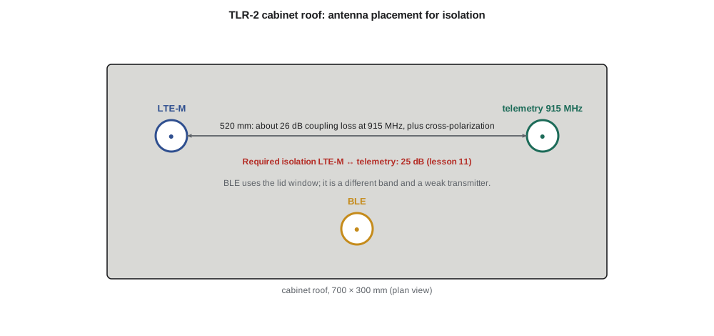
With the clock changes and the corrected cellular antenna connection, Leo's full-product test shows the telemetry receiver's sensitivity within 1 dB of its stand-alone value on every channel, with the cellular module idle or transmitting at full power, and with BLE connected. The cellular module's own sensitivity, measured by its diagnostic commands, is unaffected by telemetry transmissions within 0.5 dB, except during simultaneous transmissions, which the firmware's coordination makes rare: in a 24-hour test, the two transmitters overlapped for a total of 0.7 s. The intermodulation products at 783 and 981 MHz, measured during forced overlaps, meet the emission limits with 10 dB of margin.
The certification plan
Amara's plan has four strands, scheduled so that the hardware is frozen before the expensive tests. First, the telemetry radio is certified under RSS-247 and RSS-Gen through an ISED-recognized certification body, with RF exposure assessed under RSS-102; the antennas listed are the pole PIFA, the 6 dBi cabinet panel and the 3 dBi omnidirectional antenna that some cities prefer. Second, the cabinet and pole units are tested to ICES-003 for unintentional emissions from their digital circuits. Third, the cellular module is used within its certification conditions, including its antenna gain limits in each band; the cabinet roof antenna's gain of about 3 dBi in the low bands is within them. Fourth, the cabinet unit goes through carrier acceptance testing with the module maker's support, including over-the-air TRP and TIS measurements. The labels carry the ISED certification numbers of Cedarline's telemetry radio and of the modules, and the manual carries the required licence-exempt statements in English and French.
Because Cedarline sells in both countries, the same laboratory runs the tests to both sets of requirements in one session, and the same hardware revision is submitted for both. Amara's schedule allows eight weeks from frozen hardware to certification and another six for carrier testing, which runs in parallel with the BLE qualification listing.
The production test plan
Certification proves that the design complies; production testing proves that each unit is built like the design. Leo's production test, about 90 seconds per cabinet unit, uses a shielded test box with a coupler to each antenna port and a calibrated reference radio. It measures the telemetry transmit power and frequency error on three channels, the receive sensitivity at −105 dBm (8 dB above the specification to keep the test fast) on the same channels, the forward and reflected power detector calibration, the BLE transmit power and a connection, and the cellular module's registration with a test network simulator. Each unit's results are stored with its serial number. Leo sets the pass limits from the measured spread of the 50 pilot units, keeping each limit at least three standard deviations inside the specification so that units are not rejected for normal variation.
| Test | Method | Limit |
|---|---|---|
| Telemetry TX power, channels 0, 25, 49 | Power meter through test coupler | 27 ± 1 dBm (cabinet), 14 ± 1 dBm (pole) |
| Telemetry frequency error | Reference radio measures carrier | Within ±10 kHz |
| Telemetry RX at −105 dBm | Reference radio sends 1000 packets | At most 1 lost packet |
| Reflected-power detector | Open-circuit load applied | Fault flagged, power reduced |
| BLE TX power and connection | Reference BLE device | 0 to 8 dBm, connects within 2 s |
| Cellular registration | Network simulator | Registers on LTE-M in each enabled band |
The review's conclusion
Daniel approves the design for pilot production and certification with four open items. First, the 6 km cellular case shows that rural cabinets may need either a higher-gain directional antenna, which must be checked against the module's certification conditions, or reliance on coverage enhancement; Amara is to define the procedure. Second, the paging transmitter near 930 MHz still costs about 5 dB of sensitivity on the top channels while it transmits, as lesson 7 calculated; the hopping link tolerates it, but Priya is to test a steeper SAW filter variant. Third, Leo's survey covered twenty cabinets in one city; a second city with a different carrier must be surveyed before its order. Fourth, the field trial of TLR-1 measured the cabinet link's fading statistics only over six weeks of good weather; the TLR-2 pilot is to log signal strength through a winter of snow and ice on the antennas.
The list is typical of a successful review: no item calls the architecture into question, every item has an owner and a date, and each one is the kind of question that only field data can settle. The design that began in lesson 1 as a block diagram and a list of requirements is now a product that can be built, certified and installed.
Worked problem
Margin with a building in the path
The 6 km cellular case has 16.1 dB of margin. A building edge sits on the line of sight between the cabinet and the site. Is the 90 % reliability target still met, and what would restore it?
Show solution
- A knife edge on the line of sight costs about 6 dB (lesson 9).
- \[\text{Margin} = 16.1 - 6.0 = 10.1\ \text{dB} < 10.3\ \text{dB}\]
- Raising the cabinet antenna, choosing a higher-gain antenna within the module's certified limits, or another carrier's site in a different direction would restore the margin; coverage enhancement offers a fallback at the cost of energy and latency.
Answer: Just below target; a better antenna position or a different site is needed.
Worked problem
Production test limit from pilot data
The pilot units' transmit power at channel 25 has a mean of 27.1 dBm and a standard deviation of 0.15 dB. The specification is 27 ± 1 dBm. Are limits of 27 ± 0.6 dBm at least three standard deviations inside the specification?
Show solution
- The specification edges are 26.0 and 28.0 dBm; the test limits 26.4 and 27.6 dBm.
- \[\text{Distance of the mean from each test limit: } 0.7\ \text{and}\ 0.5\ \text{dB} = 4.7\sigma\ \text{and}\ 3.3\sigma\]
- The test limits are 0.4 dB inside each specification edge, and normal units sit at least 3.3σ from the nearer test limit, so false rejections are rare and the margin to the specification protects against measurement error.
Answer: Yes.
Common mistakes
MistakeTreating certification as the last step after the design is finished.
InsteadPre-compliance testing and the antenna list shape the design; certification plans start with the architecture.
MistakeChanging an antenna or module connection after certification without review.
InsteadChanges outside the approval conditions require new testing; even a pad change can affect coexistence.
MistakeSetting production limits equal to the specification.
InsteadLimits sit inside the specification to absorb measurement error; normal spread should rarely fail them.
MistakeClosing a design review with no open items.
InsteadQuestions that only field data can answer should be listed, owned and dated.
Summary and key terms
- The TLR-2 design combines the receiver line-up, LNA, PA, matching, filters, synthesizer and antennas developed in lessons 1 to 8.
- All five links meet their margins: 49.8, 41.9, 26.7, 16.1 and 19.8 dB against 20, 20, 10.3, 10.3 and 10 dB.
- Harmonics meet the restricted-band limit with at least 12 dB of margin across all hopping channels.
- Coexistence fixes (clock frequencies, shielding, correct duplexer connection, transmit coordination) keep desensitization under 1 dB.
- Certification covers the telemetry radio under RSS-247, RSS-Gen and RSS-102, unintentional emissions under ICES-003, the modules within their conditions and carrier acceptance.
- Production tests verify each unit against limits set inside the specification from pilot data.
- Design review
- A formal check of a design against its requirements by people other than the designers.
- Pre-compliance testing
- Informal emission and performance tests made before formal certification testing.
- Production test
- A short test applied to every manufactured unit to confirm it matches the design.
- Pilot production
- A small first build used to confirm the manufacturing process and set test limits.
- Power control
- Adjustment of transmit power to the level a link actually needs.
- Carrier acceptance
- Testing required by a cellular network operator before a device may use its network.
- Open item
- A question recorded at a review with an owner and a date for its resolution.
- Test coupler
- A fixture that connects a radio port to test equipment with known loss.
Practice problems
Work each problem on paper first, then reveal the answer to check.
What margin would the pole link have if bus shadowing were 20 dB instead of 15 dB?
Show answer
49.8 − 5 = 44.8 dB.
The cellular cable is replaced by a 12 m cable with 4.8 dB loss. What is the 3 km margin?
Show answer
26.7 − 2.4 = 24.3 dB.
Why is the production sensitivity test run at −105 dBm rather than at −113 dBm?
Show answer
A level well above sensitivity gives a fast, repeatable pass/fail with few packets.
Name two changes that would require the telemetry certification to be updated.
Show answer
A new antenna type or higher gain than listed; a higher output power or a change to the RF circuit.
How much average channel occupancy does the cabinet use in 20 s, and what is the limit?
Show answer
About 3.3 ms against 400 ms.
Why does the review ask for winter data?
Show answer
Snow and ice on antennas and seasonal foliage change losses that six summer weeks did not measure.
Lesson quiz · 5 questions
Score 60% or more to complete this lesson.
Create a free account to save your progress, take quizzes and earn a certificate.