
ELE-455 · Lesson 7 of 12 · 22 min
Mixers, oscillators and frequency synthesis
Every radio in TLR-2 needs a clean, accurate, rapidly tunable local oscillator. The telemetry transceiver hops to a new channel every few tens of milliseconds and must settle on the new frequency within a fraction of a millisecond; the cellular module tunes across bands from 700 MHz to 2.2 GHz; the BLE radio hops among 40 channels at 2.4 GHz. All of them generate their local oscillators with phase-locked frequency synthesizers built around voltage-controlled oscillators, and all of them use mixers to move signals between radio frequency and baseband. These circuits sit inside the chips and the module, so the team does not design them transistor by transistor. It does choose their crystal references, sets their loop filters, budgets their phase noise against the blockers Leo measured, and diagnoses them when a receiver misbehaves. This lesson covers what the team needs to do that well.
Mixers
A mixer multiplies two signals. Multiplying a radio-frequency signal at f_RF by a local oscillator at f_LO produces components at the sum and difference frequencies, as the trigonometric identity cos a cos b = ½[cos(a − b) + cos(a + b)] shows, and a filter keeps the one wanted. ELE-350 introduced mixing and the image problem; here we look at mixers as circuits with their own gain, noise and distortion.
Passive mixers, such as the diode ring or the switching CMOS mixer common in integrated receivers, use the LO to switch the signal path on and off. They have conversion loss rather than gain, about 4 to 7 dB for a diode ring, high linearity and, in CMOS, very low flicker noise. Active mixers such as the Gilbert cell, a differential pair whose tail current is steered by a second, switched pair, provide conversion gain and good isolation between ports, at the cost of more noise and less linearity. Switching mixers are driven by an LO that is essentially a square wave, so they also mix the signal with the LO's odd harmonics: a receiver tuned to 915 MHz with a switching mixer also responds to signals near 2745 MHz, which the front-end filters must remove.
Mixer data sheets give conversion gain, noise figure, IIP3, the 1 dB compression point, and port-to-port isolation. Isolation matters more than it might seem. LO leakage to the RF port radiates from the antenna and, in a zero-IF receiver, mixes with itself to produce a DC offset. RF leakage to the IF port lets a strong signal bypass the mixer's filtering. Second-order intercept IIP2 measures how well a mixer rejects second-order distortion, which in a zero-IF receiver converts strong amplitude-varying signals, such as the LTE uplink from a nearby phone, directly to baseband.
Oscillators
An oscillator is an amplifier with positive feedback that satisfies the Barkhausen criterion at one frequency: unity loop gain and zero loop phase. ELE-340 built Colpitts and Wien oscillators on this principle. Radio-frequency designers often use the equivalent negative-resistance view: an active circuit presents a negative resistance to a resonator, and oscillation builds up when the negative resistance exceeds the resonator's loss, until amplitude limiting brings the loop gain back to exactly one.
A voltage-controlled oscillator (VCO) adds a varactor, a diode or MOS capacitor whose capacitance changes with voltage, to its resonator. Integrated VCOs use LC tanks with on-chip inductors and cross-coupled transistor pairs as the negative resistance; their inductors have Q of only 10 to 20, which limits how clean the oscillator can be. The VCO gain K_VCO, in hertz per volt, sets how much the frequency moves for a change of tuning voltage: the telemetry chip's VCO has about 30 MHz/V.
A crystal oscillator uses a quartz resonator with a Q of 10⁴ to 10⁶ and a frequency that varies only tens of parts per million with temperature and age. It is the reference from which every other frequency in the radio is derived. The TLR-2 telemetry transceiver uses a 26 MHz crystal with a ±10 ppm tolerance and ±10 ppm stability over temperature, which keeps the 915 MHz carrier within about ±18 kHz, well inside the receiver's tolerance for a 50 kb/s GFSK signal. The cellular module needs better, about ±0.1 ppm after it has locked to the network, and uses a temperature-compensated crystal oscillator.
Phase noise
A real oscillator's output is not a single spectral line. Random fluctuations of its phase spread its power into sidebands that fall off with offset from the carrier. Phase noise L(f_m) is the power in a 1 Hz bandwidth at an offset f_m, relative to the carrier power, in dBc/Hz. Leeson's model explains its typical shape: close to the carrier, the resonator's limited Q turns the amplifier's noise into phase noise that falls at 20 dB per decade of offset, steeper still where transistor flicker noise is upconverted, and far from the carrier the noise flattens to a floor set by the amplifier and buffers.
Here F is the amplifier's effective noise factor, P_s the signal power in the resonator, Q_L the loaded Q, f₀ the oscillation frequency and f_c the flicker corner. The model shows the designer's levers: higher Q, higher signal power and lower noise. It also shows why crystal oscillators, with their enormous Q, are so much cleaner than LC VCOs.
Phase-locked frequency synthesis
A phase-locked loop (PLL) combines the agility of a VCO with the accuracy of a crystal. A phase-frequency detector compares the reference with the VCO output divided by N; a charge pump turns the phase error into current pulses; a loop filter turns them into the VCO's tuning voltage. In lock, the divided VCO frequency equals the reference, so f_VCO = N f_ref. An integer-N synthesizer changes channel by changing the integer N, so its channel spacing equals the reference frequency. For 500 kHz channels that would require a 500 kHz reference and N of 1805 to 1854, which is a problem because phase noise from the reference and detector is multiplied by N, about 20 log₁₀ N or 65 dB here, and because the loop bandwidth must stay well below the reference frequency, making hops slow.
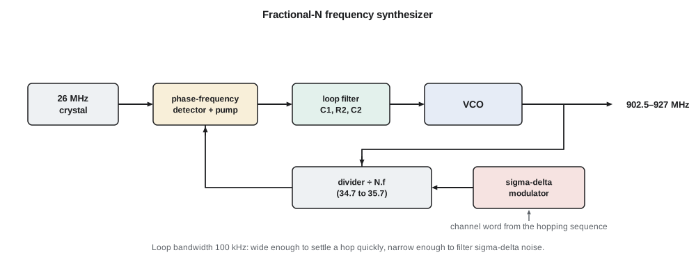
A fractional-N synthesizer solves both problems. The divider switches between N and N + 1 (or a wider range) under the control of a sigma-delta modulator so that the average division ratio has a fractional part. With a 26 MHz reference, the 50 telemetry channels need ratios from 34.712 to 35.654, which the program computes. The phase noise multiplication is only about 31 dB, and the loop bandwidth can be wide. The price is quantization noise from the dithered divider, which the sigma-delta modulator pushes to high offset frequencies where the loop filter attenuates it, and fractional spurs, discrete tones that appear when the fractional part is a simple ratio.
import math

# 1. Integer-N and fractional-N channel plans for 50 hopping channels, 902.5 to 927.0 MHz, 500 kHz apart
fref = 26e6
print("channel  f (MHz)   N (integer part)  fraction")
for ch in (0, 1, 25, 49):
    f = 902.5e6 + ch*500e3
    N = f/fref
    print(f"  {ch:3d}   {f/1e6:7.1f}       {int(N):3d}          {N - int(N):.5f}")
print(f"integer-N would need a {500e3/1e3:.0f} kHz reference: N = {902.5e6/500e3:.0f} to {927.0e6/500e3:.0f}")

# 2. Integrate a synthesizer phase-noise profile to rms phase error and jitter at 915 MHz
prof = [(1e3, -85), (1e4, -92), (1e5, -100), (1e6, -122), (1e7, -142)]   # offset Hz, dBc/Hz
def L(f):
    for (f1, l1), (f2, l2) in zip(prof, prof[1:]):
        if f1 <= f <= f2:
            return l1 + (l2 - l1)*math.log10(f/f1)/math.log10(f2/f1)
    return prof[-1][1]
area = 0.0; n = 4000
lo, hi = math.log10(1e3), math.log10(1e7)
for k in range(n):
    f1 = 10**(lo + (hi - lo)*k/n); f2 = 10**(lo + (hi - lo)*(k + 1)/n)
    area += 0.5*(10**(L(f1)/10) + 10**(L(f2)/10))*(f2 - f1)
phi = math.sqrt(2*area)                 # double-sideband, radians rms
print(f"integrated phase noise 1 kHz-10 MHz: {math.degrees(phi):.2f} deg rms; jitter {phi/(2*math.pi*915e6)*1e12:.2f} ps rms")

# 3. Reciprocal mixing: a strong signal 1 MHz away mixes with LO noise into the wanted channel
bw = 67.5e3; sens = -113.0
for blk_dbm in (-60, -50, -40):
    noise = blk_dbm + L(1e6) + 10*math.log10(bw)
    floor = -174 + 10*math.log10(bw) + 2.68
    desense = 10*math.log10(1 + 10**((noise - floor)/10))
    print(f"blocker {blk_dbm} dBm at 1 MHz: reciprocal-mixing noise {noise:6.1f} dBm vs floor {floor:6.1f} dBm -> desense {desense:4.1f} dB")

# 4. Second-order passive loop filter for a 100 kHz loop bandwidth, 50 deg phase margin
Kpd, Kvco, N = 2.5e-3/(2*math.pi), 30e6*2*math.pi, 35.2     # A/rad, rad/s/V, average N
wc = 2*math.pi*100e3; pm = math.radians(50)
b = (1/math.cos(pm) + math.tan(pm))**2                       # pole/zero spread for the phase margin
T1 = math.sqrt(b)/wc; T2 = 1/(wc*math.sqrt(b))                # zero and pole time constants
C1 = Kpd*Kvco/(N*wc**2)*T2/T1*math.sqrt((1 + (wc*T1)**2)/(1 + (wc*T2)**2))
C2 = C1*(T1/T2 - 1); R2 = T1/C2
print(f"loop filter: C1 {C1*1e12:.0f} pF, C2 {C2*1e9:.2f} nF, R2 {R2/1e3:.2f} kohm (zero {1/(2*math.pi*T1)/1e3:.1f} kHz, pole {1/(2*math.pi*T2)/1e3:.0f} kHz)")channel f (MHz) N (integer part) fraction
0 902.5 34 0.71154
1 903.0 34 0.73077
25 915.0 35 0.19231
49 927.0 35 0.65385
integer-N would need a 500 kHz reference: N = 1805 to 1854
integrated phase noise 1 kHz-10 MHz: 0.49 deg rms; jitter 1.50 ps rms
blocker -60 dBm at 1 MHz: reciprocal-mixing noise -133.7 dBm vs floor -123.0 dBm -> desense 0.4 dB
blocker -50 dBm at 1 MHz: reciprocal-mixing noise -123.7 dBm vs floor -123.0 dBm -> desense 2.7 dB
blocker -40 dBm at 1 MHz: reciprocal-mixing noise -113.7 dBm vs floor -123.0 dBm -> desense 9.8 dB
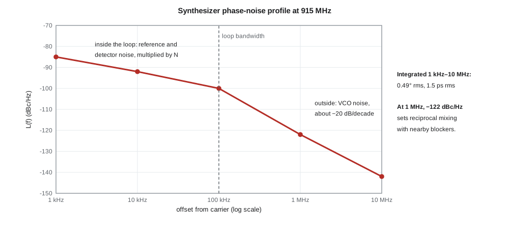
loop filter: C1 1964 pF, C2 12.86 nF, R2 0.34 kohm (zero 36.4 kHz, pole 275 kHz)The loop bandwidth is a compromise. Inside it, the PLL tracks the reference, so the output phase noise is the reference and detector noise multiplied by N; outside it, the VCO's own noise appears unfiltered. A wide loop suppresses more VCO noise and settles faster after a hop; a narrow loop filters more reference and sigma-delta noise. The telemetry chip's data sheet recommends 100 kHz, and the program designs a passive second-order loop filter for that bandwidth with a 50° phase margin: C₁ about 2 nF, C₂ about 12.9 nF and R₂ about 340 Ω, with the zero at 36 kHz and the extra pole at 275 kHz. These standard-formula values are a starting point that Priya refines in the chip maker's simulation tool, which includes the sigma-delta noise.
What phase noise does to a radio
Phase noise matters in three ways. It adds jitter to the LO, which smears the received constellation; integrating the profile from 1 kHz to 10 MHz gives 0.49° rms or 1.5 ps rms at 915 MHz, negligible for binary GFSK and far below what QPSK or 16-QAM would tolerate.
Second, in a transmitter, phase noise at large offsets falls in neighbouring channels and bands and counts as an unwanted emission. Third, and most important for TLR-2, it causes reciprocal mixing in the receiver. A strong blocker at an offset Δf mixes with the LO's phase noise at the same offset, and the product lands on top of the wanted signal as if it were noise. The added noise power is the blocker power plus the phase noise at Δf plus 10 log₁₀ of the channel bandwidth.
With L(1 MHz) = −122 dBc/Hz and a 67.5 kHz channel, a blocker at −60 dBm, 1 MHz away, adds noise 10 dB below the receiver's own noise floor and desensitizes it by only 0.4 dB. At −50 dBm the desensitization is 2.7 dB, and at −40 dBm it is 9.8 dB. Leo's survey found the paging transmitter near 930 MHz at −35 dBm at the cabinet antenna, 2 MHz above the top channel. Its effect on channels near the top of the band is a real concern, and lesson 11 and the capstone return to it with the hopping plan, since a hopping link can avoid a few channels at the band edge.
Worked problem
Reciprocal mixing from the paging transmitter
The paging signal is −35 dBm at the antenna and passes the SAW with 2 dB loss. Channel 49 at 927 MHz is 3 MHz away, where the LO phase noise is about −131 dBc/Hz. Find the reciprocal-mixing noise referred to the input and compare it with the −123 dBm noise floor.
Show solution
- \[P_{n,rm} = -37 + (-131) + 48.3 = -119.7\ \text{dBm}\]
- The receiver's own floor is −123.0 dBm, so the total is 10 log₁₀(10^{−12.30} + 10^{−11.97}) ≈ −118.0 dBm.
- \[\text{Desensitization} = -118.0 - (-123.0) = 5.0\ \text{dB}\]
Answer: About 5 dB of lost sensitivity on channel 49 while the pager transmits.
Settling time and hopping
A frequency-hopping radio must retune quickly. After a change in N, the PLL's frequency error decays with a time constant of the order of 1/(2π × loop bandwidth); for 100 kHz, roughly 1.6 µs, and settling to within a few kilohertz takes a few tens of microseconds once the VCO's coarse tuning band has been selected. The telemetry transceiver performs that band selection automatically in about 100 µs. With hops every packet and packets of 5 ms, the settling time is under 3 % of the airtime, and the firmware simply starts transmitting the preamble after the chip reports lock.
Common mistakes
MistakeThinking a mixer produces only the difference frequency.
InsteadIt produces sum and difference products, plus products with LO harmonics in switching mixers; filters select the wanted one.
MistakeChoosing an integer-N synthesizer for fine channel spacing without considering phase noise.
InsteadReference noise is multiplied by N; small references force high N and narrow loops.
MistakeIgnoring phase noise because the modulation is simple.
InsteadReciprocal mixing with strong nearby signals can desensitize any receiver, whatever its modulation.
MistakeTreating the loop filter as a component the chip maker has fixed.
InsteadLoop bandwidth trades in-band and out-of-band noise and settling time; it is chosen for the application.
Summary and key terms
- Mixers translate frequency by multiplication; passive mixers are linear, active mixers give gain; isolation and IIP2 matter in direct-conversion receivers.
- Oscillators satisfy unity loop gain and zero phase; VCOs tune with varactors; crystals provide the stable reference.
- Phase noise L(f_m) in dBc/Hz falls with offset; Leeson's model links it to Q, signal power and noise.
- A PLL makes f_VCO = N f_ref; fractional-N synthesizers give fine steps with a high reference and a sigma-delta-controlled divider.
- Loop bandwidth trades reference noise, VCO noise, spurs and settling time.
- Reciprocal mixing adds noise equal to the blocker power plus L(Δf) plus 10 log B.
- Mixer
- A circuit that multiplies two signals to translate frequency.
- Gilbert cell
- An active mixer built from differential pairs.
- Voltage-controlled oscillator (VCO)
- An oscillator whose frequency is set by a tuning voltage.
- Phase noise
- Random phase fluctuation of an oscillator, expressed in dBc/Hz at an offset.
- Phase-locked loop (PLL)
- A feedback system that locks an oscillator's phase to a reference.
- Fractional-N synthesizer
- A PLL whose divide ratio averages a non-integer value.
- Reciprocal mixing
- Conversion of a strong blocker into in-channel noise by LO phase noise.
- Fractional spur
- A discrete tone created by the periodic pattern of a fractional divider.
Practice problems
Work each problem on paper first, then reveal the answer to check.
A 900 MHz receiver uses a switching mixer. Name a signal frequency it may respond to besides 900 MHz.
Show answer
About 2700 MHz, through the LO's third harmonic.
With a 26 MHz reference, what divide ratio gives 910.0 MHz?
Show answer
35.0 exactly, an integer channel.
By how much is reference noise multiplied in a synthesizer with N = 35?
Show answer
20 log₁₀ 35 ≈ 30.9 dB.
A blocker at −45 dBm sits 1 MHz away; L(1 MHz) = −125 dBc/Hz and B = 100 kHz. Find the reciprocal-mixing noise.
Show answer
−45 − 125 + 50 = −120 dBm.
Give two reasons to widen a PLL loop bandwidth.
Show answer
Faster settling after a hop and more suppression of VCO noise.
A 26 MHz crystal is 15 ppm high. How far off is a 915 MHz carrier derived from it?
Show answer
About 13.7 kHz high.
Lesson quiz · 5 questions
Score 60% or more to complete this lesson.
Create a free account to save your progress, take quizzes and earn a certificate.