
ELE-360 · Lesson 5 of 12 · 26 min
Faraday's law and time-varying fields
Lessons 2 to 4 kept charges still and currents steady. In that world, electric and magnetic fields are separate: charges make E, currents make B, and neither field cares about the other. The moment a magnetic field changes, that separation ends. A changing magnetic flux through a loop induces a voltage round it, and the induced electric field curls round the changing flux like the magnetic field curls round a current. Michael Faraday found this in 1831, and almost every electrical machine since has depended on it: generators, transformers, induction motors, wireless chargers and the humble loop detector. Faraday's law is also behind most of the interference problems an electronics engineer meets, because a fast-changing current in one place induces unwanted voltages in every nearby loop.
This lesson explains how the loop detector actually detects a car, a question lesson 4 left open, and then turns Faraday's law on the APS-2's electrostatic discharge problem from the other side: once the discharge current flows, what voltage does its changing magnetic field induce in the circuits next to it?
Faraday's law
Faraday's law says that the electromotive force round a closed path equals the negative rate of change of the magnetic flux through any surface bounded by the path. The electromotive force, or emf, is the circulation of the electric field, ∮E·dl, measured in volts. For a coil of N turns, the flux linkage NΦ replaces Φ. The flux can change because the field changes in time, which is transformer emf, or because the path moves or deforms in a field, which is motional emf; the law covers both. Using Stokes' theorem, the differential form at a point is ∇×E = −∂B/∂t: wherever B changes in time, the electric field has curl.
The minus sign is Lenz's law. The induced emf drives a current whose own magnetic field opposes the change in flux that caused it. Push a magnet toward a closed loop and the induced current makes a field pushing back; pull it away and the current reverses to hold the flux in. Lenz's law is a statement of energy conservation: if the induced current aided the change, it would grow without limit. It also tells you, without calculation, which way an induced current flows, which is often all a troubleshooting engineer needs.
One consequence is philosophically important and practically treacherous. In a time-varying field, the electric field is no longer conservative. The line integral of E between two points depends on the path, so 'the voltage between two points' is not uniquely defined. A voltmeter's reading depends on how its leads are routed, because the leads and the circuit form a loop, and any changing flux through that loop adds to the reading. Engineers who probe fast circuits learn this the hard way: a long ground lead on an oscilloscope probe forms a loop that picks up ringing that is not really on the circuit.
Transformers and mutual coupling
Two coils sharing flux form a transformer. A changing current i₁ in the first produces flux, part of which links the second coil and induces v₂ = M di₁/dt, where M is the mutual inductance of lesson 4. If all the flux links both coils, as in a transformer with a closed iron or ferrite core, the voltage ratio equals the turns ratio. The coupling coefficient k = M/√(L₁L₂) runs from 0 for unrelated coils to almost 1 for a good transformer. Mutual inductance is symmetric, M₁₂ = M₂₁, a reciprocity that makes it easy to compute: pick whichever direction gives the simpler flux integral.
When the second coil is short-circuited, its current obeys Lenz's law and cancels most of the flux that would otherwise link it. Seen from the first coil, the inductance falls. For a shorted secondary with negligible resistance, the first coil's effective inductance is L₁(1 − k²). With resistance R₂ in the shorted turn, the reduction depends on frequency: at low frequency the induced current is limited by R₂ and little flux is cancelled; at high frequency, where ωL₂ is much greater than R₂, the cancellation approaches its full value. In between, the shorted turn absorbs power, which appears to the first coil as added series resistance. This simple model explains the loop detector.
How the loop detects a vehicle
The car's body, floor pan, engine block and frame are good conductors. When the car stops over the loop, the detector's alternating field induces eddy currents in all of them. By Lenz's law, those currents oppose the loop's field, pushing it out of the space the metal occupies, and the loop's inductance falls. In the shorted-turn model, the car is the secondary: k² of about 1 percent for an ordinary car over a 1.8 m loop gives an inductance change of about −1 percent at the detector's operating frequency. The steel of the car is ferromagnetic and would increase the inductance through its permeability, but at tens of kilohertz the eddy-current effect dominates, so the net change is a decrease. Detectors therefore look for a rise in frequency.
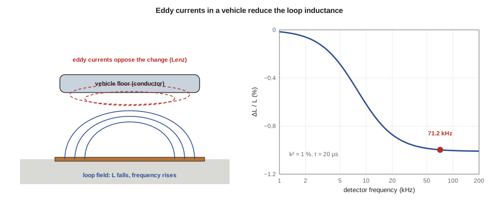
The ELE-340 detector puts the loop in a Colpitts oscillator with two 0.1 µF capacitors in series, so the frequency is 1/(2π√(L C)) with C = 0.05 µF. With 100 µH of loop and lead-in, it runs at about 71.2 kHz. A 1 percent fall in inductance raises the frequency by half a percent, about 359 Hz, which the detector's counter sees easily. A bicycle, with far less metal and poorer coupling, may change the inductance by only 0.02 percent, a frequency change of about 7 Hz, which is why bicycle detection needs careful loop layout, a sensitive detector and a road marking that shows the cyclist where to stop. Because the detector measures the fractional change, the lead-in's share of the inductance dilutes the signal, as lesson 4 showed.
Worked problem
Frequency shifts from vehicles
The detector oscillates with L = 100 µH and C = 0.05 µF. Find the operating frequency and the frequency rise for inductance changes of −1 % (car), −0.2 % (motorcycle) and −0.02 % (bicycle).
Show solution
- \[f_0 = \frac{1}{2\pi\sqrt{100\times10^{-6} \times 0.05\times10^{-6}}} = 71.18\ \text{kHz}\]
- \[f = \frac{f_0}{\sqrt{1 + \Delta L/L}} \approx f_0\Big(1 - \tfrac12\frac{\Delta L}{L}\Big)\]
- \[\Delta f_{\text{car}} \approx 71\,180 \times 0.005 = 359\ \text{Hz} \qquad \Delta f_{\text{moto}} \approx 71\ \text{Hz} \qquad \Delta f_{\text{bike}} \approx 7.1\ \text{Hz}\]
Answer: The car gives about 359 Hz, a motorcycle 71 Hz and a bicycle 7 Hz. The detector measures the period of a few hundred cycles against a crystal reference, as in ELE-340, so it can resolve fractions of a hertz, but slow drift from temperature and moisture is of the same order as the bicycle signal. The detector therefore tracks the baseline slowly and calls a detection only on a fast change.
Crosstalk between adjacent loops
An approach with three lanes has three loops side by side, each with its own lead-in in the same conduit. The loops are coupled by mutual inductance, weakly through the ground but more strongly where their lead-ins share a run. If two detectors run at nearly the same frequency, the coupling produces beats: each oscillator is pulled by the other, and the slow beat can look like a vehicle arriving and leaving. Detector manufacturers avoid this with selectable frequency settings, and installation practice is to set adjacent loops to different frequencies, twist every lead-in tightly and avoid sharing a lead-in pair between loops. The redesign Amara is working on adds automatic frequency staggering, using the TLR-1 link between cabinets to coordinate settings across neighbouring intersections.
Eddy currents, losses and shielding at low frequency
Eddy currents are not always welcome. In a transformer core, they heat the iron, which is why cores are laminated or made of high-resistivity ferrite. In a metal enclosure next to a power cable, eddy currents warm the metal slightly. The same currents are useful for shielding: a conducting sheet placed between a source of alternating magnetic field and a sensitive circuit carries eddy currents that cancel the field behind it, provided the sheet is thick compared with the depth to which the currents penetrate. Lesson 7 calls that depth the skin depth and shows it is about 8.5 mm in copper at 60 Hz but only 0.25 mm at 71 kHz, which is why a thin aluminium shield works well at radio frequencies and poorly against power-frequency hum. For low-frequency magnetic fields, high-permeability steel that diverts the flux is often the better choice.
import math
mu0 = 4e-7 * math.pi
# 1. Detector frequency and the shifts caused by vehicles
L, Cs = 100e-6, 0.05e-6             # loop + lead-in, and C1 = C2 = 0.1 uF in series
f0 = 1 / (2 * math.pi * math.sqrt(L * Cs))
print(f"detector frequency with no vehicle: {f0/1e3:.2f} kHz")
for name, dLL in (("car", -0.01), ("motorcycle", -0.002), ("bicycle", -0.0002)):
    f = 1 / (2 * math.pi * math.sqrt(L * (1 + dLL) * Cs))
    print(f"{name:10s} dL/L = {dLL*100:6.2f} %  ->  frequency rises {f - f0:7.1f} Hz")
# 2. Vehicle as a shorted secondary turn with coupling k^2 and time constant tau = L2/R2
k2, tau = 0.0101, 20e-6
print("frequency    dL/L     reflected R / (w L)")
for fk in (1, 5, 20, 71.2, 200):
    x = 2 * math.pi * fk * 1e3 * tau
    dL = -k2 * x * x / (1 + x * x)
    dR = k2 * x / (1 + x * x)
    print(f"{fk:6.1f} kHz  {dL*100:7.3f} %   {dR*100:6.3f} %")
# 3. Electrostatic discharge current coupling into a rectangular board loop beside the discharge path
I_pk, tr = 30.0, 0.8e-9             # tens of amperes rising in under a nanosecond
didt = I_pk / tr
for (w, d1, d2) in ((0.010, 0.010, 0.015), (0.005, 0.010, 0.015), (0.010, 0.020, 0.025)):
    M = mu0 * w / (2 * math.pi) * math.log(d2 / d1)      # flux of a straight current through the loop
print(f"loop {w*1e3:.0f} mm long spanning {d1*1e3:.0f}-{d2*1e3:.0f} mm: M = {M*1e9:.3f} nH, induced {M*didt:5.1f} V")detector frequency with no vehicle: 71.18 kHz car dL/L = -1.00 % -> frequency rises 358.6 Hz motorcycle dL/L = -0.20 % -> frequency rises 71.3 Hz bicycle dL/L = -0.02 % -> frequency rises 7.1 Hz frequency dL/L reflected R / (w L) 1.0 kHz -0.016 % 0.125 % 5.0 kHz -0.286 % 0.455 % 20.0 kHz -0.872 % 0.347 % 71.2 kHz -0.998 % 0.111 % 200.0 kHz -1.008 % 0.040 % loop 10 mm long spanning 10-15 mm: M = 0.811 nH, induced 30.4 V loop 5 mm long spanning 10-15 mm: M = 0.405 nH, induced 15.2 V loop 10 mm long spanning 20-25 mm: M = 0.446 nH, induced 16.7 V
The second table shows why detectors run at tens of kilohertz. With a time constant of 20 µs for the car's eddy-current paths, an assumed but reasonable value, the inductance change is negligible at 1 kHz, grows through 5 and 20 kHz and is essentially complete by 71 kHz. The reflected resistance, the power the car absorbs, peaks where ωτ = 1 and falls at higher frequencies. Detectors that measure both the frequency and the loss of the loop can use the second quantity to tell a car from a change in the pavement, and some can estimate vehicle type from the pattern of both as it drives over.
Magnetic coupling of an electrostatic discharge
Return to the APS-2 button. When the discharge arcs to the cap, the current flows from the cap along the bond strap to the enclosure. It rises by tens of amperes in under a nanosecond, so its rate of change is tens of billions of amperes per second. Any loop of circuit within a few centimetres links some of its magnetic flux. A board trace that runs from the sense input to a resistor and back to ground along a path 10 mm long, spanning 10 mm to 15 mm from the discharge path, has a mutual inductance with that path of under a nanohenry. Multiplied by the rate of change of current, that is an induced voltage of about 30 V, far beyond what a microcontroller input will take, even though no charge ever touched the trace.
Worked problem
Induced voltage in a board loop
A discharge current of 30 A rises in 0.8 ns along a straight path. A rectangular loop on the board is 10 mm long parallel to the path and spans from 10 mm to 15 mm away from it. Find the mutual inductance and the induced voltage, and the effect of halving the loop length or moving it to 20–25 mm.
Show solution
- \[\Phi = \int_{d_1}^{d_2} \frac{\mu_0 I}{2\pi\rho}\,w\,d\rho = \frac{\mu_0 I w}{2\pi}\ln\frac{d_2}{d_1} \qquad M = \frac{\mu_0 w}{2\pi}\ln\frac{d_2}{d_1}\]
- \[M = 2\times10^{-7} \times 0.010 \times \ln 1.5 = 0.811\ \text{nH}\]
- \[v = M\frac{di}{dt} = 0.811\times10^{-9} \times \frac{30}{0.8\times10^{-9}} = 30.4\ \text{V}\]
- Halving the length halves M and v, to 15.2 V; moving the loop to 20–25 mm reduces ln(d₂/d₁) from 0.405 to 0.223, giving 16.7 V.
Answer: Tens of volts from magnetic coupling alone. The fixes follow from the formula: keep the loop area small by routing each signal right over its own ground return, keep sensitive loops away from the discharge path, and route the discharge current along the outside of the enclosure so its field stays outside.
Amara turns this into a layout rule for the board: the sense trace must run directly over a solid ground plane, its loop area set by the board thickness rather than by a separate return trace, and nothing sensitive within 20 mm of the cap's bond strap. A solid plane under a trace gives the smallest possible loop, because the return current, as lesson 11 will show, flows in the plane directly beneath the trace at high frequencies. Faraday's law, applied to the right loop, is the core of most practical electromagnetic compatibility design.
Motional emf
When a conductor moves through a magnetic field, the charges in it move too and feel the force qv×B, which pushes them along the conductor. The result is a motional emf, ∮(v×B)·dl, the principle of every generator. In the signal world, motional emf is usually small. A loop lead-in vibrating in the Earth's field generates microvolts at the vibration frequency, far below the detector's band, and a bridge expansion joint flexing a saw-cut loop changes its geometry rather than generating a useful emf. It is worth knowing that both forms of induced emf, transformer and motional, come from the same law; whether a given emf is called one or the other depends only on the frame of reference.
Common mistakes
MistakeIgnoring the minus sign in Faraday's law.
InsteadLenz's law: the induced current opposes the change in flux, which fixes its direction.
MistakeExpecting a vehicle's steel to raise the loop inductance.
InsteadAt detector frequencies eddy currents dominate, so the inductance falls and the frequency rises.
MistakeAssuming voltage between two points is unique in a fast circuit.
InsteadWith changing flux, E is not conservative; the reading depends on the measurement loop.
MistakeFixing magnetic coupling with a thicker trace.
InsteadCoupling depends on loop area and distance; route signals directly over their return path and away from the aggressor.
Summary and key terms
- A changing magnetic flux through a loop induces an emf equal to −dΦ/dt; the induced electric field has curl.
- Lenz's law: induced currents oppose the change that causes them.
- In time-varying fields, E is not conservative and measured voltages depend on the measurement loop.
- Mutual inductance couples circuits; a shorted secondary reduces the primary's inductance by up to k².
- A vehicle's eddy currents lower the loop inductance by around 1 percent, raising the detector frequency by hundreds of hertz.
- Fast currents couple into nearby loops as M di/dt; small loop areas and distance are the remedies.
- Faraday's law
- The emf round a closed path equals the negative rate of change of magnetic flux through it.
- Lenz's law
- Induced currents flow so as to oppose the change in flux that produced them.
- Transformer emf
- Emf induced by a magnetic field that changes in time through a stationary loop.
- Motional emf
- Emf induced in a conductor moving through a magnetic field.
- Coupling coefficient
- k = M/√(L₁L₂), the fraction of flux shared by two coils.
- Eddy currents
- Currents induced in a conductor by a changing magnetic field.
- Crosstalk
- Unwanted coupling of a signal from one circuit into another.
Practice problems
Work each problem on paper first, then reveal the answer to check.
A 200-turn coil of area 4 cm² sits in a field changing at 5 T/s. What emf is induced?
Show answer
NA dB/dt = 200 × 4 × 10⁻⁴ × 5 = 0.4 V.
The detector loop is 90 µH with no lead-in and C = 0.05 µF. What is the frequency and the shift for a 1 % fall in L?
Show answer
75.0 kHz; about +375 Hz.
Two coils of 50 µH and 200 µH have M = 80 µH. What is k?
Show answer
80/√(50 × 200) = 0.8.
A shorted turn with k² = 0.02 and ωτ = 3. What is the fractional change in inductance?
Show answer
−0.02 × 9/10 = −1.8 %.
A current changing at 10⁹ A/s couples to a loop with M = 2 nH. What voltage is induced?
Show answer
2 V.
Which way does the induced current flow in a loop as a magnet's north pole approaches its face?
Show answer
So that the loop's own field points back toward the magnet, which seen from the magnet is anticlockwise.
Lesson quiz · 5 questions
Score 60% or more to complete this lesson.
Create a free account to save your progress, take quizzes and earn a certificate.