
ELE-280 · Lesson 8 of 12 · 25 min
Bridges and impedance measurement
Measuring a resistor of a few kilohms to 1 % is easy with any multimeter. Measuring a 10 mΩ current shunt, a strain gauge whose resistance changes by a few hundredths of a percent, or the equivalent series resistance of an electrolytic capacitor at 100 kHz is not. This lesson covers the methods built for those jobs: the four-wire Kelvin connection that removes lead resistance, the Wheatstone bridge that turns tiny resistance changes into measurable voltages, and the LCR meter that measures capacitors and inductors as complex impedances at a chosen frequency.
Two Cedarline problems motivate the lesson. The LED driver's current-sense resistor turned out, in lesson 3, to dominate the uncertainty of the current measurement, so Amara wants its actual value. And the 470 µF bulk capacitor on the 24 V rail is a common failure point in outdoor controllers, where heat dries out electrolytic capacitors, so she wants Leo to measure the capacitance and ESR of new and aged samples.
Two-wire and four-wire resistance measurement
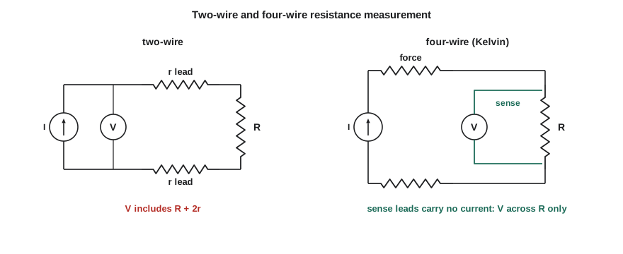
A multimeter in its ordinary two-wire resistance mode drives its test current through the same leads it uses to measure voltage. The voltage it reads therefore includes the drop across both leads and both contact resistances, typically 0.1 to 0.5 Ω in total. On a 10 kΩ resistor that is negligible. On a 2.2 Ω sense resistor it is a 5 to 20 % error, and on a 10 mΩ shunt it swamps the reading completely. Zeroing the meter with the probes shorted together helps, but contact resistance changes every time the probes are pressed.
The four-wire, or Kelvin, method separates the two jobs. One pair of leads, the force leads, carries the test current through the resistor. A second pair, the sense leads, connects to the resistor's terminals inside the force connections and measures only the voltage across the resistor itself. Because the voltmeter draws almost no current, the sense leads carry no current and drop no voltage, so their resistance does not matter. Bench meters with a 4W ohms function have four terminals for exactly this, and low-value resistors and shunts are often made with four terminals so the sense points are defined precisely.
Worked problem
Measuring the sense resistor
With a two-wire measurement, Leo reads 2.47 Ω across the nominal 2.2 Ω sense resistor. With the probes shorted, the meter reads 0.24 Ω. A four-wire measurement on the bench meter reads 2.2183 Ω. Explain the difference and find the resistor's deviation from nominal.
Show solution
- The two-wire reading includes lead and contact resistance. Subtracting the shorted-probe reading gives 2.47 − 0.24 = 2.23 Ω, but contact resistance varies by tens of milliohms between connections, so this is uncertain to a few percent.
- The four-wire reading excludes the leads entirely.
- \[\text{deviation} = \frac{2.2183 - 2.2000}{2.2000} \times 100\,\% \approx +0.83\,\%\]
Answer: The resistor is 2.218 Ω, about 0.8 % above nominal and within its 1 % tolerance. With this measured value, Leo's estimate of the LED current in lesson 3 becomes 0.41825/2.2183 ≈ 188.5 mA and its standard uncertainty drops from about 1.1 mA to about 0.2 mA. The gap to the firmware's 186 mA shrinks from 4.1 mA to 2.5 mA, still significant, which points to an offset in the firmware's analog-to-digital reading.
The Wheatstone bridge
A Wheatstone bridge is four resistors in a diamond, driven by a voltage source across one diagonal, with a voltmeter or detector across the other. When the ratio of the resistors on one side equals the ratio on the other, the two midpoints sit at the same voltage and the detector reads zero; the bridge is balanced. If three resistors are known and one is adjustable, balancing the bridge measures the fourth by a ratio, independent of the source voltage and of the detector's calibration. That was how precision resistance measurements were made for a century, and the principle survives in many instruments.
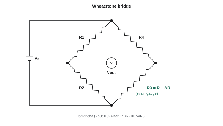
Today bridges are used mostly off balance, as a way to measure small changes. Suppose all four resistors are equal at R and one of them, a sensor, changes to R + ΔR. For small changes the output is approximately V_s·ΔR/(4R). A strain gauge on a steel bracket might change by 0.1 % under load, giving only 2.5 mV from a 10 V bridge, but that 2.5 mV sits on a zero baseline rather than on top of 5 V, so it can be amplified a thousandfold without saturating anything. Using two or four active gauges in the bridge doubles or quadruples the output and cancels temperature effects that change all the gauges equally.
Worked problem
A strain gauge on the signal mast
Cedarline is testing a strain gauge on the steel arm that carries the signal heads, to monitor wind and ice loading. The 350 Ω gauge forms one arm of a quarter bridge with three 350 Ω fixed resistors and a 5.0 V excitation. Under an ice load, the gauge's resistance rises by 0.12 %. Find the bridge output with the exact formula and the small-change approximation.
Show solution
- The gauge resistance is 350 × 1.0012 = 350.42 Ω, in the R₃ position.
- \[V_{out} = 5.0\Big(\frac{350.42}{350.42 + 350} - \frac{350}{700}\Big) = 5.0\,(0.5002998 - 0.5000000) \approx 1.499\ \text{mV}\]
- \[V_{out} \approx \frac{V_s}{4}\frac{\Delta R}{R} = \frac{5.0}{4} \times 0.0012 = 1.500\ \text{mV}\]
Answer: About 1.50 mV. The approximation is excellent for small changes. To read it, an instrumentation amplifier with a gain of about 1,000 brings it to 1.5 V for the controller's ADC.
Impedance and the LCR meter
Capacitors and inductors are never pure. A real capacitor has an equivalent series resistance (ESR) from its leads, plates and electrolyte, an equivalent series inductance from its leads and construction, and a leakage resistance in parallel. A real inductor has winding resistance and capacitance between turns. Their impedances therefore depend on frequency, and measuring them means measuring a complex impedance Z = R + jX at a chosen test frequency, which is what an LCR meter does. It applies a small AC test signal, measures the current and voltage magnitudes and the phase between them, and computes the impedance, then reports it as the user chooses: capacitance and ESR, inductance and series resistance, dissipation factor D, quality factor Q, or the magnitude and phase directly.
An LCR meter lets you choose the equivalent circuit, series or parallel, and the two give different numbers for the same impedance. The convention is to use the series model for low impedances, such as large capacitors and small inductors, where the series resistance matters most, and the parallel model for high impedances, such as small capacitors and large inductors, where leakage dominates. For electrolytic capacitors, ESR at 100 kHz and capacitance at 120 Hz, the ripple frequency of a full-wave rectifier on a 60 Hz supply, are the standard figures on data sheets. LCR meters also use four-terminal connections, often called Kelvin clips, so that lead impedance does not corrupt low-impedance readings, and they let you perform open and short corrections to subtract the fixture.
# Kelvin vs two-wire, quarter-bridge output, and capacitor ESR from an LCR-style measurement
import math
R_true, r_lead = 2.2183, 0.12
print(f"two-wire reads {R_true + 2*r_lead:.4f} ohm, four-wire reads {R_true:.4f} ohm")

def bridge(vs, r1, r2, r3, r4):
    return vs * (r3 / (r3 + r4) - r2 / (r1 + r2))

for strain_pct in (0.01, 0.05, 0.12, 0.5):
    rg = 350 * (1 + strain_pct / 100)
    exact = bridge(5.0, 350, 350, rg, 350)
    approx = 5.0 / 4 * strain_pct / 100
    print(f"dR/R {strain_pct:5.2f} %: exact {exact*1e3:7.4f} mV, approx {approx*1e3:7.4f} mV")

# LCR measurement of a 470 uF electrolytic: |Z| and phase at two frequencies
for label, f, zmag, theta_deg in (("new, 120 Hz", 120, 2.832, -88.6), ("new, 100 kHz", 100e3, 0.0420, -2.0),
                                  ("aged, 120 Hz", 120, 4.06, -84.3), ("aged, 100 kHz", 100e3, 0.380, -1.0)):
    th = math.radians(theta_deg)
    Rs, Xs = zmag * math.cos(th), zmag * math.sin(th)
    w = 2 * math.pi * f
    if f < 1000:
        Cs = -1 / (w * Xs)
        print(f"{label:14s}: ESR {Rs*1e3:7.1f} mohm, Cs {Cs*1e6:7.1f} uF, D = {Rs/abs(Xs):.3f}")
    else:   # reactance is a tiny fraction of |Z|, so |Z| is essentially the ESR
print(f"{label:14s}: ESR {Rs*1e3:7.1f} mohm, reactance only {abs(Xs)*1e3:.1f} mohm")two-wire reads 2.4583 ohm, four-wire reads 2.2183 ohm dR/R 0.01 %: exact 0.1250 mV, approx 0.1250 mV dR/R 0.05 %: exact 0.6248 mV, approx 0.6250 mV dR/R 0.12 %: exact 1.4991 mV, approx 1.5000 mV dR/R 0.50 %: exact 6.2344 mV, approx 6.2500 mV new, 120 Hz : ESR 69.2 mohm, Cs 468.5 uF, D = 0.024 new, 100 kHz : ESR 42.0 mohm, reactance only 1.5 mohm aged, 120 Hz : ESR 403.2 mohm, Cs 328.3 uF, D = 0.100 aged, 100 kHz : ESR 379.9 mohm, reactance only 6.6 mohm
The capacitor results tell a story Amara has seen before. At 120 Hz the new capacitor measures about 468 µF with a dissipation factor of 0.024; the aged one, taken from a controller that spent eight summers in a sun-baked cabinet, measures about 330 µF with D = 0.10. At 100 kHz the impedance is almost purely resistive, because the capacitive reactance has fallen far below the ESR, so the magnitude there is essentially the ESR: about 42 mΩ new and 380 mΩ aged. The aged capacitor's ESR is nine times higher. With 1 A of ripple current, it would dissipate about 0.38 W instead of 0.04 W, heating itself and drying out faster. ESR rising faster than capacitance falls is the typical signature of electrolytic wear-out, which is why ESR meters are standard tools for repairing power supplies.
Self-resonance and test conditions
Every capacitor has some series inductance, so above a certain frequency it stops behaving as a capacitor at all. The self-resonant frequency, where the capacitive and inductive reactances cancel, is 1/(2π√(LC)); above it, the part is an inductor. A 100 nF ceramic decoupling capacitor with 1 nH of inductance resonates near 16 MHz; a 470 µF electrolytic with 20 nH resonates in the tens of kilohertz. Measurements must therefore state their frequency, and a capacitor's value at 1 kHz says little about its behaviour at 10 MHz. Ceramic capacitors add another trap: the class II dielectrics used for high values lose a large fraction of their capacitance as DC bias voltage rises, so a 10 µF part on a 5 V rail may behave like 4 µF. An LCR meter with a DC bias option measures that directly.
Worked problem
Which equivalent circuit?
An LCR meter at 1 kHz measures a component as |Z| = 15.9 kΩ at a phase angle of −89.0°. Find the series and parallel equivalent capacitances and resistances, and decide which model suits it.
Show solution
- Series model: R_s = |Z| cos θ = 15,900 × cos(−89.0°) ≈ 277 Ω and X_s = |Z| sin θ ≈ −15,898 Ω.
- \[C_s = \frac{1}{2\pi(1000)(15\,898)} \approx 10.0\ \text{nF}, \qquad D = \frac{277}{15\,898} \approx 0.0175\]
- Parallel model: the admittance is Y = 1/Z, with conductance G = cos θ/|Z| and susceptance B = −sin θ/|Z|.
- \[R_p = \frac{1}{G} \approx 911\ \text{k}\Omega, \qquad C_p = \frac{B}{2\pi f} \approx 10.0\ \text{nF}\]
Answer: Both models give about 10.0 nF because D is small. The impedance is high, so the parallel model is the conventional choice and R_p ≈ 0.9 MΩ describes the dielectric loss as a shunt resistance. For low-loss parts the two capacitance values agree; for lossy ones they differ, and the report must say which model was used.
Common mistakes
MistakeMeasuring low resistances with two wires.
InsteadUse the four-wire Kelvin method; lead and contact resistance can be larger than the resistor.
MistakeTreating a bridge output as proportional to strain for large changes.
InsteadThe output is linear only for small ΔR/R; use the exact formula or linearization for large changes.
MistakeReporting capacitance without the test frequency.
InsteadReal capacitors depend on frequency; state the frequency, level and, for ceramics, the DC bias.
MistakeChoosing the wrong equivalent circuit on an LCR meter.
InsteadUse series for low impedances and parallel for high impedances, and say which you used.
MistakeSkipping the open and short fixture corrections.
InsteadCorrect for the fixture before measuring, or its impedance is included in the result.
Summary and key terms
- Two-wire resistance readings include lead and contact resistance; four-wire Kelvin connections remove them.
- A Wheatstone bridge balances when the resistor ratios match; off balance, its output is about V_s·ΔR/(4R) for one active arm.
- Bridges let tiny resistance changes, such as from strain gauges, be amplified from a zero baseline.
- Real capacitors and inductors have parasitic resistance, inductance and capacitance, so their impedance depends on frequency.
- An LCR meter measures complex impedance at a chosen frequency and reports C, L, ESR, D or Q in a series or parallel model.
- Self-resonance, DC bias and test conditions must be stated with any component measurement.
- Four-wire (Kelvin) measurement
- A resistance measurement with separate force and sense leads, so lead resistance does not affect the result.
- Wheatstone bridge
- A circuit of four impedances in a diamond whose output is zero when the ratios of the two sides are equal.
- Strain gauge
- A resistor whose resistance changes in proportion to the strain of the surface it is bonded to.
- Equivalent series resistance (ESR)
- The resistance in series with an ideal capacitance in a capacitor's series model.
- Dissipation factor
- The ratio of a component's series resistance to its reactance, D = R_s/|X_s|.
- LCR meter
- An instrument that measures inductance, capacitance and resistance as a complex impedance at a chosen frequency.
- Self-resonant frequency
- The frequency at which a component's parasitic inductance and capacitance cancel.
Practice problems
Work each problem on paper first, then reveal the answer to check.
A two-wire reading of a 0.100 Ω shunt shows 0.37 Ω. Explain.
Show answer
Lead and contact resistance add about 0.27 Ω; use a four-wire measurement.
A quarter bridge of 120 Ω gauges with 10 V excitation sees ΔR/R = 0.05 %. Estimate the output.
Show answer
10/4 × 0.0005 = 1.25 mV.
A balanced bridge has R₁ = 1 kΩ, R₂ = 2 kΩ and R₃ = 5 kΩ. Find R₄.
Show answer
R₄ = R₃·R₁/R₂ = 2.5 kΩ.
At 100 kHz, a capacitor measures |Z| = 0.05 Ω at θ = −5°. Estimate its ESR.
Show answer
0.05 cos 5° ≈ 0.050 Ω.
Find the self-resonant frequency of a 1 µF capacitor with 2 nH of series inductance.
Show answer
1/(2π√(2 × 10⁻¹⁵)) ≈ 3.6 MHz.
Why are electrolytic capacitor capacitances usually specified at 120 Hz?
Show answer
It is the ripple frequency of a full-wave rectifier on a 60 Hz supply, where bulk capacitors do their main job.
Lesson quiz · 5 questions
Score 60% or more to complete this lesson.
Create a free account to save your progress, take quizzes and earn a certificate.