
ELE-280 · Lesson 5 of 12 · 26 min
Power supplies and function generators
Most measurements need a source as well as a meter. The bench power supply provides the DC rails a circuit runs on, and the function generator provides the test signals: sine waves to measure a frequency response, square waves to see a step response, pulses to trigger logic, and ramps to sweep a sensor input. Both instruments look like simple boxes with knobs, and both have behaviours that surprise people the first time: a supply that suddenly drops its voltage, a generator whose output is twice what its display says. This lesson explains what the instruments actually do, so that the source is never the hidden cause of a strange result.
This week Leo powers up a fresh prototype controller board for the first time, then drives its microphone amplifier with test tones to check its gain. Amara watches the first power-up, because a first power-up is the moment a wiring or assembly fault is most likely to cost a board.
The bench power supply: constant voltage and constant current
A typical laboratory DC supply has two settings for each output: a voltage setpoint and a current limit. It regulates whichever one is reached first. With a light load, the output sits at the voltage setpoint and the current is whatever the load draws; this is constant-voltage (CV) mode. If the load tries to draw more than the current limit, the supply reduces its output voltage until the current equals the limit; this is constant-current (CC) mode. The front panel shows which mode is active, usually with a CV or CC indicator. The crossover happens at the load resistance R = V_set / I_limit.
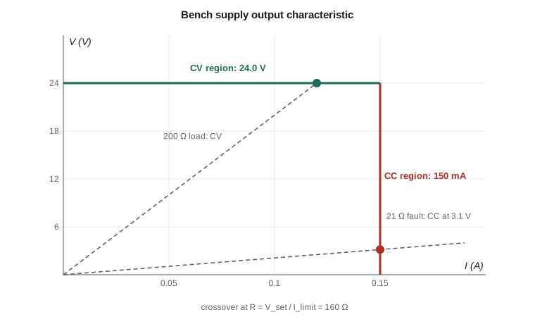
The current limit is the most useful safety feature on the bench. Before connecting a new or untested board, set the voltage, then set the current limit to a little more than the board is expected to draw, and only then connect. If there is a short circuit or a reversed part, the supply drops into CC mode, the voltage collapses and the fault draws only the limited current, often too little to damage anything. A supply left at its maximum current of several amperes will happily burn a trace, a reversed capacitor or a regulator before you notice.
Worked problem
Setting the limit for a first power-up
The controller board is expected to draw about 120 mA from 24 V with its LEDs off and about 350 mA with all signal heads lit. Amara sets 24.0 V and a 150 mA limit for the first power-up. On connection, the supply shows 3.1 V and 150 mA with the CC light on. What does that indicate, and what resistance does the board present?
Show solution
- The supply is in CC mode, so the board is drawing at least the 150 mA limit at only 3.1 V.
- \[R = \frac{V}{I} = \frac{3.1\ \text{V}}{0.150\ \text{A}} \approx 21\ \Omega\]
- A healthy board at 24 V and 120 mA presents about 200 Ω, and at 3.1 V it would draw far less than 150 mA.
Answer: The board looks like about 21 Ω, nearly a short. There is a fault on the 24 V rail: a reversed diode or capacitor, a solder bridge or a damaged regulator. Because of the limit, only about half a watt is dissipated in the fault, and Leo can find it with a thermal camera, a finger test on cool parts or by measuring resistance with the power off.
The fault in the example turned out to be the input protection diode, fitted backwards during assembly. Reversed, it conducted from the rail to ground. With the limit set at 3 A, it would have overheated and failed short or open within seconds, and the failure might have taken the input trace with it.
Sensing, ripple and output details
A supply regulates the voltage at its own terminals, but the board sees the voltage after the leads. With 1 A flowing through a metre of thin lead, there can be 0.1 V or more of drop in each direction. Many supplies have remote-sense terminals: a second pair of wires that measures the voltage at the load, so the supply raises its output to compensate for lead drop. For most bench work, short, thick leads and measuring at the board are enough. Other specifications to know are ripple and noise, the AC on the DC output, which is a few millivolts on a good linear supply and more on a switching supply; transient response, how quickly the output recovers when the load current steps; and whether the outputs are floating, so they can be stacked in series for higher or bipolar voltages.
Floating outputs make bipolar rails easy. To power an op-amp circuit from ±12 V, connect the positive terminal of one output to the negative terminal of the other and call that junction ground. The free positive terminal is then +12 V and the free negative terminal −12 V. A supply's chassis ground terminal, usually green, connects to the mains safety ground; whether you tie the circuit ground to it depends on the setup, and lesson 7 explains the consequences for oscilloscope measurements.
The function generator
A modern function generator is usually an arbitrary waveform generator built on direct digital synthesis. A phase accumulator steps through a waveform table at a rate set by the desired frequency, and a digital-to-analog converter and filter turn the samples into a smooth output. It can produce sine, square, triangle, ramp, pulse, noise and user-defined waveforms, with control of frequency, amplitude, DC offset, duty cycle and rise time, and often modulation, sweeps and bursts. Its specifications include frequency range and resolution, amplitude accuracy and flatness across frequency, harmonic distortion for sine waves, rise time for square waves, and jitter.
The 50 Ω output and the doubling surprise
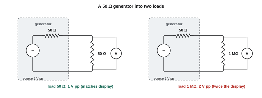
Almost every function generator has a 50 Ω output impedance: an internal voltage source in series with 50 Ω. That matches the coaxial cables and terminations used in radio and high-speed work, where a 50 Ω source driving a 50 Ω cable into a 50 Ω load gives clean, reflection-free signals. The generator's display assumes that 50 Ω load by default. It sets its internal source to twice the displayed amplitude, so that the 50 Ω divider leaves the displayed value across the load. If you connect the output to a high-impedance input instead, such as an oscilloscope set to 1 MΩ or an op-amp input, there is almost no current, no drop across the internal 50 Ω, and the voltage you see is twice what the display says.
Worked problem
The microphone amplifier test
Leo sets the generator to a 1 kHz sine of 20 mV peak-to-peak and connects it to the microphone amplifier input, which has an input resistance of 10 kΩ. The amplifier is designed for a gain of 40. The oscilloscope at the output shows 1.6 V peak-to-peak. Leo concludes that the gain is 80. What is wrong, and what is the real gain?
Show solution
- With the generator's load setting at the default of 50 Ω, its internal source is set to 2 × 20 = 40 mV peak-to-peak.
- The amplifier's 10 kΩ input forms a divider with the 50 Ω output resistance.
- \[v_{in} = 40\ \text{mV} \times \frac{10\,000}{10\,000 + 50} \approx 39.8\ \text{mV peak-to-peak}\]
- \[A_v = \frac{1.6\ \text{V}}{0.0398\ \text{V}} \approx 40\]
Answer: The input was really about 40 mV peak-to-peak, not 20 mV, so the gain is about 40, as designed. Leo should either set the generator's load to high-Z, so the display matches the open-circuit voltage, or, better, measure the input with a second oscilloscope channel instead of trusting the display.
The fix is a menu setting: most generators let you declare the load as high-Z, and then the display shows the open-circuit voltage. Even so, the safest habit is never to trust a source's display for a measurement that matters. Measure the voltage actually arriving at the device under test with the oscilloscope or meter, and compute gain, attenuation or response from two measured values. That habit also catches the cases where the load is neither 50 Ω nor high impedance, such as an amplifier input of a few hundred ohms, where the true voltage is somewhere in between.
# Voltage actually delivered by a 50-ohm generator into various loads
def delivered(display_vpp, load_ohm, setting="50"):
    rs = 50.0
    source = 2 * display_vpp if setting == "50" else display_vpp   # internal open-circuit amplitude
    return source * load_ohm / (load_ohm + rs)

for load in (50, 600, 10e3, 1e6):
    v50 = delivered(0.020, load, "50")
    vhz = delivered(0.020, load, "highZ")
    print(f"load {load:>9.0f} ohm: display 20 mV pp -> {v50*1e3:6.2f} mV pp (50-ohm setting), "
          f"{vhz*1e3:6.2f} mV pp (high-Z setting)")

# Supply crossover: which mode does each load put the supply in?
vset, ilim = 24.0, 0.150
for rload in (1000, 200, 160, 50, 21):
    i_cv = vset / rload
    if i_cv <= ilim:
        print(f"R = {rload:5d} ohm: CV, {vset:.1f} V, {i_cv*1e3:6.1f} mA")
    else:
print(f"R = {rload:5d} ohm: CC, {ilim*rload:.1f} V, {ilim*1e3:6.1f} mA")load 50 ohm: display 20 mV pp -> 20.00 mV pp (50-ohm setting), 10.00 mV pp (high-Z setting) load 600 ohm: display 20 mV pp -> 36.92 mV pp (50-ohm setting), 18.46 mV pp (high-Z setting) load 10000 ohm: display 20 mV pp -> 39.80 mV pp (50-ohm setting), 19.90 mV pp (high-Z setting) load 1000000 ohm: display 20 mV pp -> 40.00 mV pp (50-ohm setting), 20.00 mV pp (high-Z setting) R = 1000 ohm: CV, 24.0 V, 24.0 mA R = 200 ohm: CV, 24.0 V, 120.0 mA R = 160 ohm: CV, 24.0 V, 150.0 mA R = 50 ohm: CC, 7.5 V, 150.0 mA R = 21 ohm: CC, 3.1 V, 150.0 mA
The output confirms that the high-Z setting gives the right number for the oscilloscope and the 10 kΩ amplifier input but is off by half for a true 50 Ω load, while the 50 Ω setting is right only for a 50 Ω load. Neither setting is right for a 600 Ω audio input. The supply section shows the crossover at 160 Ω for a 24 V, 150 mA setting, and the 21 Ω fault giving 3.15 V in CC mode, close to what the panel showed.
Other generator features worth knowing
A square wave from a generator is not perfectly square: its rise time, often a few nanoseconds, limits the fastest edge you can test with, and the 50 Ω source driving a long unterminated cable can show reflections and ringing on the edges. The DC offset control adds a fixed level, which is how you produce a 0-to-3.3 V logic signal instead of a ±1.65 V one; make sure the offset is zero when driving an AC-coupled amplifier input you do not want to bias. The sync or trigger output provides a clean logic-level pulse once per cycle, ideal for triggering an oscilloscope when the main signal is noisy or small. Many generators also turn their output off at power-up; forgetting to press the output button explains many silent first measurements.
Worked problem
Making a logic-level test signal
Leo needs a 0 to 3.3 V, 10 kHz square wave to simulate a push-button debouncer input with a high-impedance CMOS gate. How should he set the generator if its load is set to high-Z?
Show solution
- A square wave from 0 to 3.3 V has an amplitude of 3.3 V peak-to-peak.
- Its centre, the average of the high and low levels, is 1.65 V, so the DC offset is 1.65 V.
- With the load set to high-Z and a CMOS input of many megohms, the display matches the voltage at the gate.
Answer: Square, 10 kHz, 3.3 V peak-to-peak, offset 1.65 V, high-Z load. Many generators also have a pulse or high-level/low-level mode that lets him enter 3.3 V and 0 V directly. He should check the levels on the scope before connecting, so that a stray negative swing does not stress the gate's input protection.
Common mistakes
MistakePowering a new board with the current limit at maximum.
InsteadSet the limit just above the expected current before connecting; a fault then draws only the limited current.
MistakeMissing that the supply has dropped into constant-current mode.
InsteadWatch the CV/CC indicator; a CC light on a board that should draw little current signals a fault or an undersized limit.
MistakeTrusting the generator display when driving a high-impedance input.
InsteadWith the default 50 Ω setting, a high-impedance load receives twice the displayed amplitude; set high-Z or measure the actual input.
MistakeForgetting the generator's DC offset.
InsteadCheck the offset; an unwanted offset can saturate an amplifier or forward-bias input protection.
MistakeMeasuring rail voltage at the supply terminals under heavy load.
InsteadMeasure at the board, or use remote sense; lead resistance drops voltage.
Summary and key terms
- A bench supply regulates voltage until the load demands more than the current limit, then regulates current; the crossover is at R = V_set/I_limit.
- Setting a low current limit before the first power-up limits the damage from wiring and assembly faults.
- Lead drop, ripple, transient response and floating outputs affect what the circuit actually receives.
- Function generators use direct digital synthesis to produce sine, square, pulse, ramp, noise and arbitrary waveforms.
- Generators have a 50 Ω output; with the default load setting, a high-impedance load receives twice the displayed amplitude.
- Measure the signal at the device under test rather than trusting a source's display.
- Constant-voltage mode
- Supply operation in which the output voltage is held at the setpoint and the current is set by the load.
- Constant-current mode
- Supply operation in which the current is held at the limit and the voltage falls to whatever the load allows.
- Current limit
- The maximum current a bench supply will deliver before switching to constant-current mode.
- Remote sense
- A pair of wires that lets a supply regulate the voltage at the load rather than at its terminals.
- Direct digital synthesis
- Generation of waveforms by stepping through a stored table at a programmable rate and converting the samples to analog.
- Output impedance
- The internal series impedance of a source; 50 Ω for most function generators.
- High-Z setting
- A generator setting that makes the displayed amplitude equal to the open-circuit output voltage.
Practice problems
Work each problem on paper first, then reveal the answer to check.
A supply is set to 12 V and 0.5 A. What load resistance marks the CV/CC crossover?
Show answer
24 Ω.
The same supply drives a 10 Ω load. What are the output voltage and current?
Show answer
CC mode: 0.5 A and 5 V.
A generator set to 1 V peak-to-peak with a 50 Ω load setting drives an oscilloscope at 1 MΩ. What does the scope show?
Show answer
About 2 V peak-to-peak.
What does the same generator deliver into a 600 Ω load?
Show answer
2 × 600/650 ≈ 1.85 V peak-to-peak.
How would you make ±15 V from two floating 15 V outputs?
Show answer
Connect the positive of one to the negative of the other as ground; the free terminals are +15 V and −15 V.
Why is measuring the input with a scope better than trusting the generator display?
Show answer
The actual input depends on the load impedance, cable and settings; measuring removes all of those assumptions.
Lesson quiz · 5 questions
Score 60% or more to complete this lesson.
Create a free account to save your progress, take quizzes and earn a certificate.