
ELE-202 · Lesson 7 of 12 · 34 min
Dependent sources, amplifier models and two-port networks
Dependent sources were introduced in Lesson 1 as idealized elements whose value is set by a voltage or current elsewhere in the circuit. They are the language engineers use to describe amplification: every transistor, op amp, sensor interface and power converter controller is modelled, at least for small signals, by a network of resistors and dependent sources. This lesson uses that language to build amplifier models, find the input and output resistance of circuits that contain dependent sources, and describe any linear block by its two-port parameters, so that complex systems can be analysed as chains of simple boxes.
The four dependent sources
A dependent (controlled) source produces a voltage or current proportional to a controlling voltage or current:
- Voltage-controlled voltage source (VCVS): \(v = \mu\,v_{x}\), with dimensionless voltage gain \(\mu\). An ideal voltage amplifier.
- Current-controlled current source (CCCS): \(i = \beta\,i_{x}\), with dimensionless current gain \(\beta\). A simple model of a bipolar transistor.
- Voltage-controlled current source (VCCS): \(i = g_{m}\,v_{x}\), with transconductance \(g_{m}\) in siemens. The standard model of a MOSFET.
- Current-controlled voltage source (CCVS): \(v = r_{m}\,i_{x}\), with transresistance \(r_{m}\) in ohms. A model of the transimpedance amplifier (Lesson 8).
Dependent sources are linear elements, so nodal, mesh and Thévenin analysis all apply. Two cautions from Lesson 2 still hold: never "turn off" a dependent source when applying superposition or finding a Thévenin resistance, and always express the controlling variable in terms of the circuit's unknowns.
Amplifier models
Any linear amplifier, however complex inside, can be described at its terminals by three numbers: input resistance \(R_{in}\), open-circuit voltage gain \(A_{vo}\) and output resistance \(R_{out}\). The model is a resistor at the input, and at the output a VCVS of value \(A_{vo}v_{in}\) in series with \(R_{out}\).
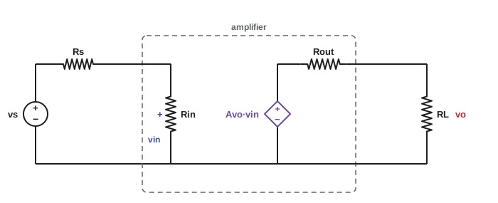
Loading occurs at both ends: the source resistance and \(R_{in}\) form a divider at the input, and \(R_{out}\) and the load form another at the output. The overall gain is
A good voltage amplifier therefore has \(R_{in} \gg R_{s}\) and \(R_{out} \ll R_{L}\). Current amplifiers want the opposite: low input resistance and high output resistance.
Worked problem
Gain in a real system
A sensor with an open-circuit voltage of 10 mV and an internal resistance of 1 kΩ drives an amplifier with \(R_{in} = 9\) kΩ, \(A_{vo} = 100\) and \(R_{out} = 100\) Ω, which drives a 900 Ω load. Find the input voltage, the output voltage and the overall gain.
Show solution
- Input divider: \(v_{in} = 10 \times 9/(1 + 9) = 9\) mV.
- Open-circuit output: \(100 \times 9 = 900\) mV.
- Output divider: \(v_{o} = 900 \times 900/(100 + 900) = 810\) mV.
- Overall gain: \(810/10 = 81\).
Answer: The amplifier is rated at a gain of 100, but the system achieves 81, because 10% of the signal is lost at each end. Matching the resistances at each interface is as important as the gain itself.
Worked problem
Cascading two stages
Two identical stages of the amplifier above are connected in cascade, from the same sensor to the same 900 Ω load. What is the overall gain?
Show solution
- Stage 1 input: \(v_{in1} = 10 \times 9/10 = 9\) mV; its output drives stage 2's 9 kΩ input.
- Stage 1 output: \(100 \times 9 \times 9/(0.1 + 9) = 890.1\) mV.
- Stage 2 output: \(100 \times 890.1 \times 900/1000 = 80{,}110\) mV = 80.1 V.
- Overall gain: \(80.1/0.010 = 8{,}011\).
Answer: About 8,000, against an ideal of \(100^{2} = 10{,}000\). (In a real circuit, 80 V would far exceed the supply and the amplifier would saturate; the point is the loading arithmetic.) Each interface in a chain is a divider, and the model makes every loss visible.
Resistance of circuits with dependent sources
When a circuit contains dependent sources, its input or Thévenin resistance cannot be found by combining resistors. Use a test source: switch off independent sources only, apply a test voltage \(v_{t}\) (or test current \(i_{t}\)) to the terminals, solve for the resulting current (or voltage), and take the ratio \(R = v_{t}/i_{t}\). Dependent sources can make the result larger or smaller than any resistor in the circuit, and even negative.
Worked problem
A resistance changed by feedback
A 2 kΩ resistor connects terminal a to ground, carrying current \(i_{x}\) downward. A dependent current source injects \(0.5\,i_{x}\) into node a. Find the resistance seen at terminal a.
Show solution
- Apply \(v_{t}\) at a. Then \(i_{x} = v_{t}/2000\).
- KCL at a: current in from the test source plus current from the dependent source equals current down the resistor: \(i_{t} + 0.5\,i_{x} = i_{x}\).
- So \(i_{t} = 0.5\,i_{x} = v_{t}/4000\), and \(R = v_{t}/i_{t} = 4\) kΩ.
Answer: 4 kΩ, twice the only resistor in the circuit, because the dependent source supplies half the resistor's current. If the dependent source supplied more than \(i_{x}\) (gain above 1), the test source would have to absorb current and the resistance would be negative: the circuit would supply power. Negative resistance is the principle behind oscillators.
Transistor small-signal models
Transistors are nonlinear, but for small signals around a fixed operating point they behave linearly and are modelled with dependent sources (ELE-240 develops the models in detail):
- A MOSFET is modelled by a VCCS \(g_{m}v_{gs}\) from drain to source, with an output resistance \(r_{o}\) in parallel and an open circuit at the gate.
- A bipolar transistor is modelled by a resistance \(r_{\pi}\) between base and emitter and a CCCS \(\beta i_{b}\) (or equivalently a VCCS \(g_{m}v_{be}\)) from collector to emitter.
Worked problem
A common-source amplifier
A MOSFET with \(g_{m} = 5\) mS and \(r_{o} = 50\) kΩ has a 10 kΩ drain resistor \(R_{D}\). The input signal drives the gate directly. Find the small-signal voltage gain and output resistance.
Show solution
- The VCCS \(g_{m}v_{gs}\) flows into the parallel combination \(r_{o} \parallel R_{D} = 50 \times 10/60 = 8.33\) kΩ.
- Gain: \(A_{v} = -g_{m}(r_{o} \parallel R_{D}) = -5 \times 10^{-3} \times 8{,}333 = -41.7\).
- Output resistance: \(R_{out} = r_{o} \parallel R_{D} = 8.33\) kΩ.
Answer: A gain of −41.7 (the minus sign means the output is inverted) and an output resistance of 8.33 kΩ. The same dependent-source analysis underlies every transistor amplifier.
Two-port networks
Many circuits have an input pair of terminals and an output pair: amplifiers, filters, transformers, transmission lines, sensor interfaces. A two-port network is described completely, for linear circuits, by four parameters relating the two port voltages \(v_{1}, v_{2}\) and currents \(i_{1}, i_{2}\) (both currents defined as flowing into the network). Different parameter sets choose different pairs as independent variables:
| Parameters | Equations | Typical use |
|---|---|---|
| Impedance (z) | v₁ = z₁₁i₁ + z₁₂i₂; v₂ = z₂₁i₁ + z₂₂i₂ | Series-connected networks; T networks |
| Admittance (y) | i₁ = y₁₁v₁ + y₁₂v₂; i₂ = y₂₁v₁ + y₂₂v₂ | Parallel-connected networks; transistors at high frequency |
| Hybrid (h) | v₁ = h₁₁i₁ + h₁₂v₂; i₂ = h₂₁i₁ + h₂₂v₂ | Bipolar transistor data sheets |
| Transmission (ABCD) | v₁ = Av₂ − Bi₂; i₁ = Cv₂ − Di₂ | Cascaded networks, power lines |
Each parameter is found by setting one port to an open or short circuit. For example, \(z_{11} = v_{1}/i_{1}\) with port 2 open (\(i_{2} = 0\)), and \(z_{21} = v_{2}/i_{1}\) also with port 2 open.
Worked problem
z-parameters of a T network
A T network has a 2 Ω series arm at port 1, a 3 Ω series arm at port 2, and a 6 Ω shunt arm in the middle. Find its z-parameters.
Show solution
- \(z_{11}\): port 2 open, so \(i_{1}\) flows through 2 Ω and 6 Ω: \(z_{11} = 8\) Ω.
- \(z_{21}\): port 2 open, \(v_{2}\) is the voltage across the 6 Ω arm: \(z_{21} = 6\) Ω.
- By the same reasoning from port 2: \(z_{22} = 3 + 6 = 9\) Ω and \(z_{12} = 6\) Ω.
Answer: \(z_{11} = 8\) Ω, \(z_{12} = z_{21} = 6\) Ω, \(z_{22} = 9\) Ω. The equality \(z_{12} = z_{21}\) holds for every network of resistors, capacitors, inductors and transformers (reciprocal networks); circuits with dependent sources, such as amplifiers, are generally not reciprocal.
Worked problem
Using h-parameters
A bipolar transistor in common-emitter connection has \(h_{ie} = 2.5\) kΩ, \(h_{fe} = 100\), and negligible \(h_{re}\) and \(h_{oe}\). It drives a 2 kΩ collector load. Find the current gain and the voltage gain.
Show solution
- With \(h_{oe} \approx 0\), the output current is \(h_{fe}i_{b}\): current gain \(A_{i} = 100\).
- Input voltage: \(v_{be} = h_{ie}i_{b}\). Output voltage: \(v_{ce} = -h_{fe}i_{b}R_{L}\).
- Voltage gain: \(A_{v} = -h_{fe}R_{L}/h_{ie} = -100 \times 2/2.5 = -80\).
Answer: A current gain of 100 and a voltage gain of −80. Data sheets for small-signal bipolar transistors give h-parameters precisely because they can be measured easily with these open and short conditions.
Cascading with transmission parameters
When two-ports are connected in a chain, the output of each feeding the input of the next, their ABCD matrices simply multiply: \(\mathbf{T} = \mathbf{T}_{1}\mathbf{T}_{2}\cdots\mathbf{T}_{n}\). A series resistance \(R\) has \(\mathbf{T} = \begin{bmatrix} 1 & R \\ 0 & 1 \end{bmatrix}\) and a shunt conductance \(G\) has \(\mathbf{T} = \begin{bmatrix} 1 & 0 \\ G & 1 \end{bmatrix}\). The input resistance with a load \(R_{L}\) is \((AR_{L} + B)/(CR_{L} + D)\), and the open-circuit voltage gain is \(1/A\).
import numpy as np

def series(R):
    return np.array([[1.0, R], [0.0, 1.0]])

def shunt(R):
    return np.array([[1.0, 0.0], [1.0 / R, 1.0]])

def input_resistance(T, RL):
    A, B, C, D = T.ravel()
    return (A * RL + B) / (C * RL + D)

section = series(1000) @ shunt(1000)        # one rung of an R-R ladder, 1 kOhm each
for n in [1, 2, 3, 5, 10]:
    T = np.linalg.matrix_power(section, n)
    A = T[0, 0]
    print(f"{n:>2} sections: Rin(open end) = {input_resistance(T, 1e15):7.1f} ohm, "
          f"open-circuit gain = {1 / A:.6f}")
print(f"Infinite ladder: {1000 * (1 + 5**0.5) / 2:.1f} ohm")1 sections: Rin(open end) = 2000.0 ohm, open-circuit gain = 0.500000 2 sections: Rin(open end) = 1666.7 ohm, open-circuit gain = 0.200000 3 sections: Rin(open end) = 1625.0 ohm, open-circuit gain = 0.076923 5 sections: Rin(open end) = 1618.2 ohm, open-circuit gain = 0.011236 10 sections: Rin(open end) = 1618.0 ohm, open-circuit gain = 0.000091 Infinite ladder: 1618.0 ohm
With each added section the input resistance approaches 1,618 Ω, the infinite-ladder value from Lesson 3, while the voltage reaching the far end falls rapidly. The gains 1/2, 1/5, 1/13 and so on involve the Fibonacci numbers, a curiosity that follows from the matrix multiplication. Power engineers use exactly this method, with impedances instead of resistances, to model long transmission lines as chains of short sections (ELE-380).
Common mistakes
MistakeTurning off dependent sources when finding Thévenin resistance.
InsteadTurn off independent sources only and use a test source.
MistakeQuoting an amplifier's rated gain as the system gain.
InsteadInclude the input and output loading dividers.
MistakeAssuming a resistance found with a dependent source must be positive.
InsteadDependent sources can give any resistance, including negative.
MistakeMixing up current directions in two-port parameters.
InsteadDefine both port currents as flowing into the network.
MistakeMultiplying ABCD matrices in the wrong order.
InsteadMultiply from the source end to the load end.
Summary and key terms
- VCVS, CCCS, VCCS and CCVS model amplification; they are linear elements.
- Amplifiers are modelled by Rin, Avo and Rout; loading at each interface reduces system gain.
- Use a test source to find resistance in circuits with dependent sources; results may exceed every resistor or be negative.
- MOSFETs and BJTs are modelled for small signals with dependent sources: Av = −gm(ro ∥ RD).
- Two-port z, y, h and ABCD parameters describe linear blocks at their terminals.
- Reciprocal passive networks have z₁₂ = z₂₁.
- ABCD matrices of cascaded two-ports multiply.
- Dependent source
- A source whose value is set by a voltage or current elsewhere in the circuit.
- Transconductance
- Output current per unit input voltage, in siemens.
- Input resistance
- The resistance seen looking into an amplifier's input.
- Output resistance
- The Thévenin resistance seen looking back into an amplifier's output.
- Open-circuit voltage gain
- Output voltage per unit input voltage with no load.
- Test source
- A voltage or current applied to find a resistance.
- Negative resistance
- A terminal behaviour in which current flows out as voltage rises.
- Two-port network
- A circuit described by the voltages and currents at two terminal pairs.
- Reciprocal network
- A network whose transfer parameters are equal in both directions.
- ABCD parameters
- Transmission parameters that multiply for cascaded two-ports.
Practice problems
Work each problem on paper first, then reveal the answer to check.
Which dependent source models a MOSFET?
Show answer
A voltage-controlled current source.
Rs = 2 kΩ, Rin = 18 kΩ. Fraction of the source voltage reaching the input?
Show answer
0.9.
Avo = 50, Rout = 50 Ω, RL = 450 Ω, vin = 20 mV. Output?
Show answer
0.9 V.
A 1 kΩ resistor carrying ix to ground, with a source injecting 0.75 ix into the node. Input resistance?
Show answer
4 kΩ.
Same circuit with 1.5 ix injected. Input resistance?
Show answer
−2 kΩ.
gm = 2 mS, ro = 100 kΩ, RD = 25 kΩ. Voltage gain?
Show answer
−40.
T network: 5 Ω, 5 Ω series arms, 10 Ω shunt. z₁₁ and z₂₁?
Show answer
15 Ω and 10 Ω.
hfe = 150, hie = 3 kΩ, RL = 1.2 kΩ. Voltage gain?
Show answer
−60.
ABCD of a 10 Ω series resistor?
Show answer
[[1, 10], [0, 1]].
A = 4. Open-circuit voltage gain?
Show answer
0.25.
Lesson quiz · 5 questions
Score 60% or more to complete this lesson.
Create a free account to save your progress, take quizzes and earn a certificate.