
ELE-202 · Lesson 2 of 12 · 36 min
Kirchhoff's laws
Element laws such as Ohm's law describe each component on its own. To solve a circuit, we also need laws that describe how the components are connected. In 1845, the German physicist Gustav Kirchhoff, then a 21-year-old student, stated two such laws. One expresses conservation of charge, the other conservation of energy. Together with the element laws, they are all that is needed to solve any lumped circuit, however large. Every method in the rest of this course, including nodal analysis, mesh analysis and the circuit theorems, is a systematic way of applying them.
This chapter defines the vocabulary of circuit topology, states Kirchhoff's laws, and uses them to derive series and parallel combinations, voltage and current dividers, and the wye-delta transformation. It ends with circuits containing dependent sources, which need nothing new except one extra equation.
Nodes, branches and loops
Analysing a circuit starts with its topology, the pattern of connections, independent of what the elements are:
- A branch is a single two-terminal element, such as a resistor or a source.
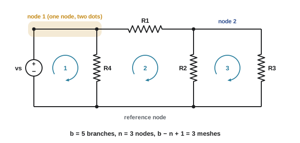
- A node is a point where two or more branches connect. All the wire between elements counts as part of one node, because ideal wires have no resistance and therefore no voltage difference along them. A common beginner's error is to count two dots joined by a wire as two nodes.
- A loop is any closed path through the circuit that passes through no node more than once.
- A mesh is a loop that encloses no other branch: one of the "window panes" of a circuit drawn flat (a planar circuit).
For a connected circuit with \(b\) branches and \(n\) nodes, there are exactly \(b - n + 1\) independent loops, which is also the number of meshes. This relation tells us how many independent equations each method in Lesson 4 will produce.
Kirchhoff's current law (KCL)
Charge cannot accumulate at a node, because a node is just a junction of ideal wires with no ability to store charge. So whatever current flows in must flow out. Kirchhoff's current law states:
The algebraic sum of the currents entering any node is zero, with currents leaving counted as negative entering. Equivalently, the sum of currents entering equals the sum leaving. KCL also applies to any closed boundary drawn around part of a circuit, called a supernode or cut set: the net current crossing the boundary is zero. This generalized form is often a shortcut.
Worked problem
Applying KCL
At a node, currents of 5 A and 4 A enter, and currents of 2 A and \(i_x\) leave. Find \(i_x\). Then, if \(i_x\) had been drawn as entering, what value would be found?
Show solution
- Entering = leaving: \(5 + 4 = 2 + i_x\).
- \(i_x = 7\) A, leaving.
- With the reference arrow reversed (entering): \(5 + 4 + i_x = 2\), so \(i_x = -7\) A.
Answer: 7 A leaving, or equivalently −7 A entering. The physical current is the same; only the reference direction changed, and the sign records that.
Kirchhoff's voltage law (KVL)
Voltage between two points is the energy per unit charge needed to move between them, and that does not depend on the path taken. Going around any closed loop and returning to the starting point, the net change in potential must be zero. Kirchhoff's voltage law states:
To apply KVL, choose a starting point and a direction around the loop, then add each element's voltage: count it as a drop (positive) if you enter the element at its + reference terminal, and as a rise (negative) if you enter at its − terminal. Any consistent convention works, provided it is used for every element in the loop.
A useful consequence: the voltage between any two nodes can be found by adding the element voltages along any path between them. Elements connected in parallel share the same two nodes, so they must have the same voltage.
Worked problem
Applying KVL
Going clockwise around a loop, a 20 V source is entered at its − terminal, then a resistor with \(v_1 = 8\) V is entered at +, then a resistor with \(v_2\) unknown is entered at +, then a 3 V source is entered at +. Find \(v_2\).
Show solution
- Sum of voltages, drops positive: \(-20 + 8 + v_2 + 3 = 0\).
- \(v_2 = 9\) V.
Answer: \(v_2 = 9\) V. The 20 V source raises the potential, and the resistors and the 3 V source share the drop: \(8 + 9 + 3 = 20\).
Series and parallel combinations
Elements are in series when they carry the same current: they are connected end to end with nothing else attached at the nodes between them. Elements are in parallel when they share the same pair of nodes and so have the same voltage. Kirchhoff's laws turn these definitions into simple combination rules.
Resistors in series
For \(N\) resistors in series carrying current \(i\), KVL gives \(v = iR_1 + iR_2 + \dots + iR_N\), so the combination behaves as one resistor:
Resistors in parallel
For resistors in parallel with voltage \(v\), KCL gives \(i = v/R_1 + v/R_2 + \dots\), so conductances add:
For two resistors, \(R_{\text{eq}} = R_1R_2/(R_1 + R_2)\), "product over sum", written \(R_1 \parallel R_2\). The parallel combination is always smaller than the smallest resistor.
Sources combine too, with care. Voltage sources in series add (with signs); current sources in parallel add. Voltage sources of different values must never be put in parallel, and current sources of different values must never be put in series, because the circuit would violate KVL or KCL.
Voltage and current dividers
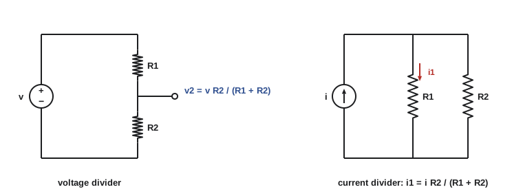
Two results occur so often that they are worth memorizing. In a series chain of resistors across voltage \(v\), the voltage across one of them is its share of the total resistance:
In a set of parallel resistors carrying total current \(i\), the current in one of them is its share of the total conductance; for two resistors,
Note the "opposite" resistor in the numerator: more current takes the path of less resistance.
Worked problem
Series-parallel reduction
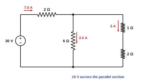
A 30 V source feeds a 2 Ω resistor in series with a parallel combination of a 6 Ω resistor and a branch made of 1 Ω and 2 Ω in series. Find the source current, the voltage across the parallel part, the current in each parallel branch, and check the power balance.
Show solution
- Series branch: \(1 + 2 = 3\) Ω. In parallel with 6 Ω: \(6 \times 3/(6 + 3) = 2\) Ω.
- Total: \(R_{\text{eq}} = 2 + 2 = 4\) Ω. Source current \(I = 30/4 = 7.5\) A.
- Voltage across the parallel part: \(7.5 \times 2 = 15\) V (or by voltage divider: \(30 \times 2/4\)).
- Currents: 6 Ω branch \(15/6 = 2.5\) A; 3 Ω branch \(15/3 = 5\) A. KCL: \(2.5 + 5 = 7.5\). ✓
- Powers absorbed: 2 Ω series \(7.5^2 \times 2 = 112.5\) W; 6 Ω: 37.5 W; 1 Ω: 25 W; 2 Ω in branch: 50 W. Total 225 W.
- Source supplies \(30 \times 7.5 = 225\) W. ✓
Answer: I = 7.5 A; 15 V across the parallel section; 2.5 A in the 6 Ω branch and 5 A in the 1 Ω + 2 Ω branch; 225 W supplied and absorbed.
Worked problem
A loaded voltage divider
Two 10 kΩ resistors divide 24 V to produce 12 V for a sensor input. The sensor has an input resistance of 10 kΩ. What voltage does it actually receive?
Show solution
- Unloaded: \(24 \times 10/(10 + 10) = 12\) V.
- Loaded: the lower 10 kΩ is now in parallel with the 10 kΩ input: \(10 \parallel 10 = 5\) kΩ.
- New output: \(24 \times 5/(10 + 5) = 8\) V.
Answer: 8 V, not 12 V. A divider only gives its unloaded ratio when the load resistance is much larger (say 100 times) than the divider resistors. This loading effect is one of the main reasons for the buffer amplifiers of Lesson 8.
The wye-delta transformation
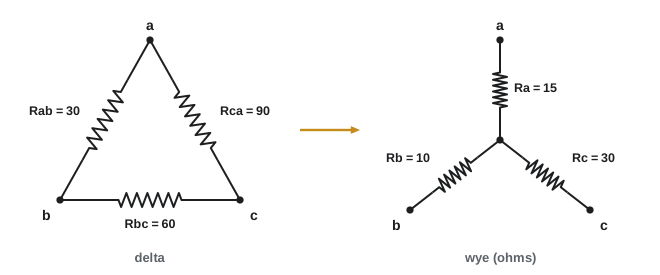
Some networks contain resistors that are neither in series nor in parallel. The classic case is a bridge, where the resistors form a triangle (delta, Δ, also called pi) or a three-pointed star (wye, Y, also called tee). A delta and a wye connecting the same three terminals can be made exactly equivalent from the outside. For a delta with resistors \(R_{ab}\), \(R_{bc}\) and \(R_{ca}\) between terminals a, b and c, the equivalent wye has, from each terminal to the centre point:
Each wye resistor is the product of the two delta resistors touching that terminal, divided by the sum of all three. The reverse transformation, from wye to delta, is \(R_{ab} = (R_aR_b + R_bR_c + R_cR_a)/R_c\), and similarly for the others: the sum of the pairwise products divided by the opposite wye resistor. Power engineers use the same idea for wye- and delta-connected three-phase loads and transformers.
Worked problem
Resistance of an unbalanced bridge
Terminals a, b and c are joined by a delta: \(R_{ab} = 30\) Ω, \(R_{bc} = 60\) Ω, \(R_{ca} = 90\) Ω. A 20 Ω resistor connects b to terminal d, and a 40 Ω resistor connects c to d. Find the resistance between a and d.
Show solution
- No two resistors are simply in series or parallel, so convert the delta to a wye. Sum = 180 Ω.
- \(R_a = 30 \times 90/180 = 15\) Ω; \(R_b = 30 \times 60/180 = 10\) Ω; \(R_c = 60 \times 90/180 = 30\) Ω.
- Now from a: 15 Ω to the centre point, then two parallel paths to d: \(10 + 20 = 30\) Ω and \(30 + 40 = 70\) Ω.
- \(30 \parallel 70 = 2100/100 = 21\) Ω.
- \(R_{ad} = 15 + 21 = 36\) Ω.
Answer: 36 Ω. (Nodal analysis in Lesson 4 gives the same result, a useful check.)
The Wheatstone bridge
A bridge whose two dividers produce the same voltage at their midpoints is balanced: no current flows in the middle branch, which can be removed or shorted without changing anything. The Wheatstone bridge exploits this to measure an unknown resistance precisely. With \(R_1\) and \(R_2\) forming one divider and \(R_3\) and the unknown \(R_x\) the other, arranged so that \(R_1\) faces \(R_3\) and \(R_2\) faces \(R_x\), the bridge balances when
For example, with \(R_1 = 100\) Ω, \(R_2 = 250\) Ω and \(R_3\) adjusted to 120 Ω for balance, \(R_x = 250 \times 120/100 = 300\) Ω. Strain gauges, pressure sensors and resistance temperature detectors (RTDs) are routinely read with bridge circuits, because a small change in one arm produces a small, easily amplified voltage across the middle.
Circuits with dependent sources
Dependent sources obey KCL and KVL like everything else. The only extra step is to write the controlling variable in terms of the unknowns.
Worked problem
KCL with a current-controlled current source
A 12 A independent current source feeds node \(v\) (relative to the reference node). Three branches leave the node to the reference: a 4 Ω resistor carrying \(i_1\), a dependent current source of value \(i_1\) (directed away from the node), and a second 4 Ω resistor. Find \(v\), \(i_1\) and the power of each element.
Show solution
- KCL at the node (leaving = entering): \(v/4 + i_1 + v/4 = 12\).
- Controlling variable: \(i_1 = v/4\).
- Substitute: \(v/4 + v/4 + v/4 = 12\), so \(3v/4 = 12\) and \(v = 16\) V. Then \(i_1 = 4\) A.
- Powers: each 4 Ω absorbs \(16^2/4 = 64\) W; the dependent source carries 4 A from the node to the reference with 16 V across it, absorbing \(16 \times 4 = 64\) W.
- The independent source supplies \(16 \times 12 = 192\) W. Check: \(-192 + 64 + 64 + 64 = 0\). ✓
Answer: \(v = 16\) V, \(i_1 = 4\) A. The independent source supplies 192 W, shared equally by the two resistors and the dependent source.
Common mistakes
MistakeCounting two dots joined by a wire as separate nodes.
InsteadAll wire between elements is a single node; redraw the circuit to merge them before counting.
MistakeMixing sign conventions within one KVL equation.
InsteadChoose a direction and a rule (drop = +) and apply it to every element in the loop.
MistakeTreating resistors as in series when a third branch connects at the node between them.
InsteadSeries elements must carry the same current, with nothing else attached at the shared node.
MistakeUsing the wrong resistor in the current-divider numerator.
InsteadFor two branches, \(i_1 = i R_2/(R_1 + R_2)\): the other branch's resistance goes on top.
MistakeAssuming a divider delivers its unloaded voltage to a load.
InsteadA load in parallel with the lower resistor changes the ratio; include it in the calculation.
Summary and key terms
- A branch is one element, a node is a junction (all connecting wire counts as one node), and a mesh is a loop enclosing no other branch; there are \(b - n + 1\) independent loops.
- KCL: the currents entering any node (or closed boundary) sum to zero.
- KVL: the voltages around any closed loop sum to zero.
- Series resistances add; parallel conductances add; two in parallel give \(R_1R_2/(R_1 + R_2)\).
- Voltage divider: \(v_k = vR_k/\sum R\). Current divider: \(i_1 = iR_2/(R_1 + R_2)\).
- Loading a divider changes its output; include the load.
- Delta-to-wye: \(R_a = R_{ab}R_{ca}/(R_{ab} + R_{bc} + R_{ca})\), and similarly for the others.
- A balanced Wheatstone bridge has no middle current: \(R_x = R_2R_3/R_1\).
- Dependent sources need one extra equation for the controlling variable.
- Branch
- A single two-terminal element in a circuit.
- Node
- A connection point of two or more branches, including all wire joining them.
- Loop
- A closed path that passes through no node more than once.
- Mesh
- A loop in a planar circuit that encloses no other branch.
- KCL
- Kirchhoff's current law: the sum of currents entering a node is zero.
- KVL
- Kirchhoff's voltage law: the sum of voltages around a closed loop is zero.
- Series
- Elements carrying the same current, connected end to end with no other branch between them.
- Parallel
- Elements connected between the same two nodes, sharing the same voltage.
- Equivalent resistance
- A single resistance with the same terminal behaviour as a network of resistors.
- Voltage divider
- Series resistors that split a voltage in proportion to their resistances.
- Current divider
- Parallel resistors that split a current in proportion to their conductances.
- Loading effect
- The change in a circuit's output when a load draws current from it.
- Wye-delta transformation
- Formulas converting between equivalent three-terminal star and triangle networks.
- Wheatstone bridge
- A bridge circuit used to measure resistance by balancing two dividers.
Practice problems
Work each problem on paper first, then reveal the answer to check.
A circuit has 7 branches and 4 nodes. How many independent loops does it have?
Show answer
b − n + 1 = 7 − 4 + 1 = 4.
Currents of 3 A, −2 A and 6 A enter a node (as drawn). A fourth branch's current \(i\) is drawn leaving. Find \(i\).
Show answer
i = 3 − 2 + 6 = 7 A.
Around a loop, a 15 V source is a rise and resistors drop 4 V and 6 V. What is the voltage across the remaining resistor?
Show answer
15 − 4 − 6 = 5 V.
Find the equivalent resistance of 12 Ω, 6 Ω and 4 Ω in parallel.
Show answer
G = 1/12 + 1/6 + 1/4 = 0.5 S, so R = 2 Ω.
A 48 V supply feeds 2 kΩ, 3 kΩ and 7 kΩ in series. Find the voltage across the 3 kΩ resistor.
Show answer
48 × 3/12 = 12 V.
A 9 A current divides between 3 Ω and 6 Ω in parallel. Find each current.
Show answer
i(3 Ω) = 9 × 6/9 = 6 A; i(6 Ω) = 9 × 3/9 = 3 A.
A divider of 4.7 kΩ (top) and 4.7 kΩ (bottom) across 10 V feeds a 47 kΩ load. Find the loaded output voltage.
Show answer
4.7 ∥ 47 = 4.273 kΩ; 10 × 4.273/8.973 = 4.76 V (instead of 5 V).
Convert a delta of three 12 Ω resistors to a wye.
Show answer
Each wye resistor = 12 × 12/36 = 4 Ω.
A Wheatstone bridge balances with \(R_1 = 1\) kΩ, \(R_2 = 2.2\) kΩ and \(R_3 = 470\) Ω. Find \(R_x\).
Show answer
R_x = R₂R₃/R₁ = 2200 × 470/1000 = 1034 Ω.
A 6 A source feeds a node with a 3 Ω resistor (current \(i_x\)) and a dependent source drawing \(2i_x\) to the reference. Find the node voltage.
Show answer
KCL: i_x + 2i_x = 6, so i_x = 2 A and v = 3 × 2 = 6 V.
Lesson quiz · 5 questions
Score 60% or more to complete this lesson.
Create a free account to save your progress, take quizzes and earn a certificate.