
ELE-202 · Lesson 1 of 12 · 34 min
Circuit elements
Every electrical system, from a phone charger to a data centre's power distribution to the processor inside a GPU, can be analysed as a circuit: an interconnection of idealized elements that obey simple mathematical laws. Circuit analysis is the first engineering course in electrical engineering because everything else builds on it. Electronics, power systems, control, signal processing and communications all start by drawing a circuit model and solving it.
In a CEAB-accredited Canadian engineering program, this course usually comes in second year, after first-year physics has introduced charge, fields and simple circuits. Where PHYS-131 asked "what is happening physically?", this course asks "how do we solve any circuit systematically, however large?" It also introduces the precise conventions that engineers use, so that a circuit analysed by one engineer can be checked by another, and later stamped and signed by a licensed professional engineer.
This chapter defines the basic quantities and the passive sign convention, then introduces the elements: independent and dependent sources, resistors, capacitors and inductors. Later chapters combine them with Kirchhoff's laws and develop systematic methods for solving circuits of any size.
Charge, current, voltage and power
Electric charge \(q\) is measured in coulombs (C). An electron carries \(-1.602 \times 10^{-19}\) C. Current is the rate of flow of charge past a point:
measured in amperes (A), where 1 A = 1 C/s. By convention, current direction is the direction positive charge would move, opposite to the electrons in a metal wire. In a circuit diagram, every current is given a reference direction with an arrow. The arrow is a bookkeeping choice, made before the answer is known; if the calculated current turns out negative, the actual flow is opposite to the arrow. Nothing is wrong.
Voltage (potential difference) \(v\) is the energy per unit charge required to move charge between two points:
measured in volts (V), where 1 V = 1 J/C. Voltage always exists between two points, marked on a diagram with + and − reference polarity signs. Again, the signs are a reference: a negative result means the actual polarity is reversed.
Power is the rate at which energy is delivered or absorbed. Multiplying the two definitions:
measured in watts (W). Energy over a time interval is the integral of power, \(w = \int p\, dt\), which for constant power is simply \(w = pt\).
The passive sign convention
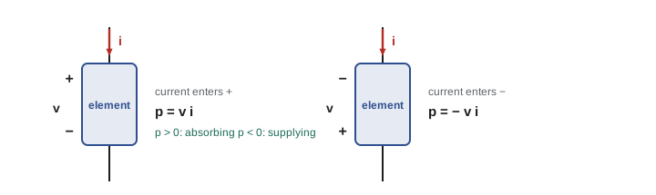
For every two-terminal element, an engineer chooses a voltage reference (+ and −) and a current reference (an arrow). The passive sign convention says: draw the current arrow entering the element at the + terminal. With that choice,
- \(p = vi > 0\) means the element absorbs power (a resistor heating, a battery charging);
- \(p = vi < 0\) means the element supplies (delivers) power to the rest of the circuit.
If the current reference instead enters at the − terminal, then \(p = -vi\). Using the convention consistently, element by element, is what lets power calculations check themselves: in any circuit, the total power absorbed by all elements is exactly zero. Every watt supplied by one element is absorbed by others.
Worked problem
Absorbing or supplying?
Using the passive sign convention, find the power absorbed by each element: (a) \(v = 12\) V, \(i = 3\) A entering the + terminal; (b) \(v = 12\) V, \(i = -2\) A entering the + terminal; (c) \(v = 5\) V, \(i = 4\) A entering the − terminal.
Show solution
- (a) Current enters +: \(p = vi = 12 \times 3 = 36\) W. Positive, so the element absorbs 36 W.
- (b) \(p = 12 \times (-2) = -24\) W. Negative: the element supplies 24 W. Physically, 2 A leaves through the + terminal, which is what a source delivering power does.
- (c) Current enters −: \(p = -vi = -5 \times 4 = -20\) W. The element supplies 20 W.
Answer: (a) absorbs 36 W; (b) supplies 24 W; (c) supplies 20 W. The sign of the result, not the element's name, tells you which way energy flows.
Sources
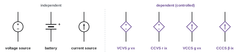
Independent sources
An ideal independent voltage source maintains a specified voltage between its terminals regardless of the current through it. The current is whatever the rest of the circuit demands. An ideal independent current source maintains a specified current through itself regardless of the voltage across it. Real sources only approximate these ideals: a battery's voltage sags under load, which can be modelled by adding a small series resistance. The ideal models are still enormously useful, and they are the building blocks for modelling real ones.
Two consequences follow from the definitions. An ideal voltage source must never be short-circuited, since that would demand infinite current; and an ideal current source must never be left open-circuited, since that would demand infinite voltage. Circuits that violate these rules have no solution, which is the mathematics telling you the model is not physical.
Dependent (controlled) sources
A dependent source has a value controlled by a voltage or current elsewhere in the circuit. Dependent sources are drawn as diamonds, and there are four kinds:
- Voltage-controlled voltage source (VCVS): \(v = \mu v_x\), where \(\mu\) is a dimensionless gain.
- Current-controlled current source (CCCS): \(i = \beta i_x\), with dimensionless \(\beta\).
- Voltage-controlled current source (VCCS): \(i = g v_x\), where \(g\) is a transconductance in siemens (S).
- Current-controlled voltage source (CCVS): \(v = r i_x\), where \(r\) is a transresistance in ohms.
Dependent sources do not appear as physical parts you can buy. They model the behaviour of active devices: a transistor behaves approximately as a current-controlled or voltage-controlled current source, and an operational amplifier as a voltage-controlled voltage source with enormous gain (Lesson 8). Whenever a circuit contains one, the analysis needs one extra equation expressing the controlling variable in terms of the circuit unknowns.
Resistors
A resistor obeys Ohm's law: the voltage across it is proportional to the current through it, \(v = iR\), with the passive sign convention. Resistance \(R\) is measured in ohms (Ω). Its reciprocal is conductance, \(G = 1/R\), measured in siemens (S), so \(i = Gv\). Conductance is convenient in parallel circuits and in nodal analysis.
A resistor always absorbs power:
which ends up as heat. Two limiting cases appear constantly. A short circuit is a connection with \(R = 0\): the voltage across it is zero whatever the current. An open circuit has \(R = \infty\) (or \(G = 0\)): the current is zero whatever the voltage.
The resistance of a uniform conductor follows from its material and geometry:
where \(\rho\) is the resistivity (Ω·m), \(L\) the length and \(A\) the cross-sectional area. Copper at 20 °C has \(\rho \approx 1.72 \times 10^{-8}\) Ω·m, so 100 m of 1.5 mm² copper wire has \(R = 1.72 \times 10^{-8} \times 100 / (1.5 \times 10^{-6}) = 1.15\) Ω.
Real resistors have a tolerance (commonly 1% or 5%), a power rating (exceeding it overheats the part), and a temperature coefficient. In circuit analysis, a resistor is linear: doubling the voltage doubles the current. Linearity is what makes the powerful theorems of Lesson 6 possible.
Capacitors
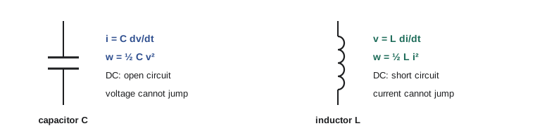
A capacitor stores energy in an electric field between two conductors separated by an insulator. Its charge is proportional to its voltage, \(q = Cv\), where capacitance \(C\) is measured in farads (F). Practical values range from picofarads to farads. Differentiating gives the capacitor's defining relation:
The current depends on how fast the voltage changes, not on the voltage itself. Three consequences follow:
- Under DC (steady, unchanging) conditions, \(dv/dt = 0\), so \(i = 0\): a capacitor acts as an open circuit.
- The voltage across a capacitor cannot change instantaneously, because that would require infinite current. This fact governs the transient behaviour studied in ELE-203.
- A capacitor stores energy \(w = \tfrac{1}{2}Cv^2\), which it can return to the circuit. An ideal capacitor dissipates nothing.
Worked problem
Capacitor current and energy
(a) The voltage across a 10 µF capacitor rises steadily from 0 to 10 V in 2 ms. What current flows? (b) How much energy does a 470 µF capacitor store at 50 V?
Show solution
- (a) \(dv/dt = 10 / 0.002 = 5000\) V/s, so \(i = C\,dv/dt = 10 \times 10^{-6} \times 5000 = 0.05\) A = 50 mA, constant while the ramp lasts.
- (b) \(w = \tfrac{1}{2}Cv^2 = 0.5 \times 470 \times 10^{-6} \times 50^2 = 0.5875\) J.
Answer: (a) 50 mA during the ramp, and zero once the voltage stops changing. (b) About 0.59 J, which is why large capacitors in power supplies can deliver a painful shock long after the equipment is unplugged.
Inductors
An inductor stores energy in a magnetic field, typically produced by current in a coil of wire. Its flux linkage is proportional to its current, \(\lambda = Li\), where inductance \(L\) is measured in henries (H). By Faraday's law, the voltage is the rate of change of flux linkage:
The inductor is the dual of the capacitor, with the roles of voltage and current exchanged:
- Under DC conditions, \(di/dt = 0\), so \(v = 0\): an inductor acts as a short circuit.
- The current through an inductor cannot change instantaneously, because that would require infinite voltage. Interrupting inductor current abruptly, for example by opening a switch in series with a relay coil or motor, produces a large voltage spike that can arc across the switch or destroy a transistor. This is why inductive loads have snubbers or flyback diodes.
- An inductor stores energy \(w = \tfrac{1}{2}Li^2\).
Worked problem
Inductor voltage and energy
The current in a 20 mH inductor rises steadily from 0 to 5 A in 1 ms. Find the voltage across it during the rise and the energy stored at the end.
Show solution
- \(di/dt = 5 / 0.001 = 5000\) A/s.
- \(v = L\,di/dt = 0.020 \times 5000 = 100\) V.
- \(w = \tfrac{1}{2}Li^2 = 0.5 \times 0.020 \times 5^2 = 0.25\) J.
Answer: 100 V during the rise and 0.25 J stored. If the same 5 A were interrupted in 10 µs, the voltage would be \(0.020 \times 5/10^{-5} = 10{,}000\) V, the origin of inductive kick.
Because this course concentrates on DC analysis, capacitors and inductors will mostly appear in their DC roles, as open and short circuits, until Lesson 10 develops them further. ELE-203 shows how they behave when voltages and currents change.
Power balance
Conservation of energy requires that, at every instant, the power supplied by some elements equals the power absorbed by the others. With the passive sign convention applied to every element, the algebraic sum of absorbed power is zero:
This is the most useful check in circuit analysis. After solving a circuit, compute the power of every element; if the sum is not zero (to rounding), there is an error somewhere.
Worked problem
Power balance with a dependent source
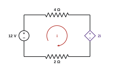
A single loop contains a 12 V independent source, a 4 Ω resistor, a current-controlled voltage source of value \(2i\) (in volts, where \(i\) is the loop current) whose polarity opposes the independent source, and a 2 Ω resistor. Find \(i\) and the power of every element.
Show solution
- Going around the loop, the 12 V source raises the potential; the resistors and the dependent source drop it: \(12 = 4i + 2i + 2i\).
- Solve: \(8i = 12\), so \(i = 1.5\) A.
- Independent source: current leaves its + terminal, so it supplies \(12 \times 1.5 = 18\) W (absorbs −18 W).
- 4 Ω: \(1.5^2 \times 4 = 9\) W absorbed. 2 Ω: \(1.5^2 \times 2 = 4.5\) W absorbed.
- Dependent source: \(v = 2i = 3\) V, with current entering its + terminal: absorbs \(3 \times 1.5 = 4.5\) W.
- Check: \(-18 + 9 + 4.5 + 4.5 = 0\). ✓
Answer: \(i = 1.5\) A. The independent source supplies 18 W; the resistors absorb 9 W and 4.5 W, and the dependent source absorbs 4.5 W. The total is zero.
Circuit models and their limits
Circuit analysis rests on the lumped-element assumption: each element is small enough that signals travel across it effectively instantly, so voltage and current are well defined at its terminals. The assumption holds when the circuit is much smaller than the wavelength of the signals in it. At 60 Hz the wavelength is about 5000 km, so any building wiring qualifies. At the gigahertz frequencies inside servers and network equipment, wavelengths are centimetres, and printed circuit traces must be treated as transmission lines. Likewise, real elements are only approximately ideal: resistors have a little inductance, capacitors have leakage, and wires have resistance. A good engineer chooses the simplest model that captures what matters and knows when it stops being valid.
How this course is organized
The course builds from single elements to complete designs:
- Lesson 2 states Kirchhoff's laws, and Lesson 3 applies them to real resistive networks: tolerances, loading, shunts, bridges and ladders.
- Lessons 4 and 5 solve any linear circuit by nodal and mesh analysis, by hand and in matrix form by computer.
- Lesson 6 covers the circuit theorems, and Lesson 7 dependent sources, amplifier models and two-port networks.
- Lessons 8 and 9 analyse op amps and their uses in sensing, comparison and data conversion.
- Lesson 10 develops capacitors and inductors, Lesson 11 power and efficiency in DC systems, and Lesson 12 the design, simulation and verification of circuits.
Common mistakes
MistakeTreating a negative calculated current or voltage as an error.
InsteadA negative result only means the actual direction or polarity is opposite to the chosen reference.
MistakeUsing \(p = vi\) when the current enters the − terminal.
InsteadWith the passive sign convention, \(p = vi\) only when current enters +; otherwise \(p = -vi\).
MistakeAssuming a source always supplies power.
InsteadA source can absorb power (a battery being charged); the sign of \(p\) decides.
MistakeTreating a capacitor as a short or an inductor as an open circuit at DC.
InsteadAt DC a capacitor is an open circuit and an inductor is a short circuit.
MistakeSkipping the power-balance check.
InsteadThe absorbed powers of all elements must sum to zero; checking catches most sign errors.
Summary and key terms
- Current \(i = dq/dt\) (A), voltage \(v = dw/dq\) (V), power \(p = vi\) (W), energy \(w = \int p\,dt\) (J).
- Reference directions and polarities are choices; negative answers mean the opposite actual direction.
- Passive sign convention: with current entering +, \(p = vi\) is absorbed power; \(p < 0\) means the element supplies power.
- Ideal independent sources fix a voltage or a current; dependent sources (VCVS, CCCS, VCCS, CCVS) are controlled by another circuit variable.
- Resistor: \(v = iR\), \(p = i^2R = v^2/R\), \(R = \rho L/A\); a short has \(R = 0\), an open has \(R = \infty\).
- Capacitor: \(i = C\,dv/dt\), \(w = \tfrac12 Cv^2\), open circuit at DC, voltage continuous.
- Inductor: \(v = L\,di/dt\), \(w = \tfrac12 Li^2\), short circuit at DC, current continuous.
- The absorbed powers of all elements sum to zero: always check.
- Current
- The rate of flow of charge, in amperes (coulombs per second).
- Voltage
- The energy per unit charge between two points, in volts (joules per coulomb).
- Reference direction
- The arrow or polarity chosen for a current or voltage before solving.
- Passive sign convention
- Choosing current to enter an element's + terminal, so that \(p = vi\) is the power absorbed.
- Ideal voltage source
- An element that maintains a specified voltage regardless of its current.
- Ideal current source
- An element that maintains a specified current regardless of its voltage.
- Dependent source
- A source whose value is controlled by a voltage or current elsewhere in the circuit.
- Conductance
- The reciprocal of resistance, in siemens.
- Short circuit
- A connection with zero resistance.
- Open circuit
- A break with infinite resistance, carrying no current.
- Resistivity
- A material property, in Ω·m, giving resistance from length and cross-section.
- Capacitance
- Charge stored per volt, in farads; a capacitor's current is \(C\,dv/dt\).
- Inductance
- Flux linkage per ampere, in henries; an inductor's voltage is \(L\,di/dt\).
- Lumped-element model
- A circuit model in which elements are small enough that signals cross them instantly.
- Power balance
- The principle that absorbed powers in a circuit sum to zero.
Practice problems
Work each problem on paper first, then reveal the answer to check.
A charge of 120 C passes a point in 1 minute. What is the average current?
Show answer
120 / 60 = 2 A.
An element has \(v = -6\) V and \(i = 2\) A entering its + terminal. Find the power absorbed.
Show answer
p = vi = −12 W: the element supplies 12 W.
A 9 V battery delivers 250 mA for 2 hours. How much energy does it supply?
Show answer
P = 2.25 W; w = 2.25 × 7200 = 16,200 J (16.2 kJ).
What is the conductance of a 2.5 kΩ resistor, and what current flows when 10 V is applied?
Show answer
G = 0.4 mS; i = Gv = 4 mA.
A 330 Ω resistor rated 0.25 W: what is the largest voltage it can safely have across it?
Show answer
v = √(PR) = √(0.25 × 330) = 9.08 V.
Find the resistance of 250 m of copper wire with a cross-section of 2.5 mm².
Show answer
R = 1.72 × 10⁻⁸ × 250 / 2.5 × 10⁻⁶ = 1.72 Ω.
A 100 µF capacitor's voltage falls from 20 V to 5 V in 3 ms at a steady rate. Find the current (with the passive sign convention) and the energy released.
Show answer
dv/dt = −5000 V/s; i = −0.5 A (the capacitor delivers current). Energy released = ½ × 10⁻⁴ × (400 − 25) = 18.75 mJ.
What current is needed to store 2 J in a 40 mH inductor?
Show answer
i = √(2w/L) = √(4/0.04) = 10 A.
A VCCS has transconductance 0.05 S and its controlling voltage is 4 V. What current does it produce?
Show answer
i = gv = 0.05 × 4 = 0.2 A.
In a series loop, a 24 V source drives 3 A through a 5 Ω resistor and an unknown element. Find the power of each element and identify whether the unknown absorbs or supplies power.
Show answer
Source supplies 72 W; resistor absorbs 45 W; the unknown must absorb 27 W (it has 9 V across it). Total: −72 + 45 + 27 = 0.
Lesson quiz · 5 questions
Score 60% or more to complete this lesson.
Create a free account to save your progress, take quizzes and earn a certificate.