
DCT-340 · Lesson 4 of 12 · 21 min
Maintenance on live systems: concurrent maintainability in practice
Most buildings are maintained by switching things off. A data centre cannot be switched off: the load runs every hour of every day, and tenants pay for it not to stop. So the plant is designed to be maintained while it runs. Every component that needs maintenance has a way to be isolated while another path carries the load. Engineers call this property concurrent maintainability, and it is the defining feature of a facility built to Uptime Institute's Tier III, or to a similar level in other rating systems. This lesson is about what concurrent maintainability means for the people who do the work: how a piece of equipment is taken out of service while the load keeps running, what risk that creates and how the risk is kept small.
What concurrent maintainability promises
A concurrently maintainable facility has at least two distribution paths for power and cooling to the critical load, and enough redundant capacity that any single component can be removed from service for planned maintenance without affecting the load. Hall A at Stonebridge is a good example. Each cabinet is fed from an A side and a B side, through separate UPS systems, switchboards and floor distribution units, as DCT-220 described. Cooling comes from twelve CRAH units where nine can carry the load. Chilled water reaches the hall from a looped header with valves that let any section be isolated. Any one UPS, switchboard, distribution unit, CRAH or pipe section can be taken out while the rest carries on.
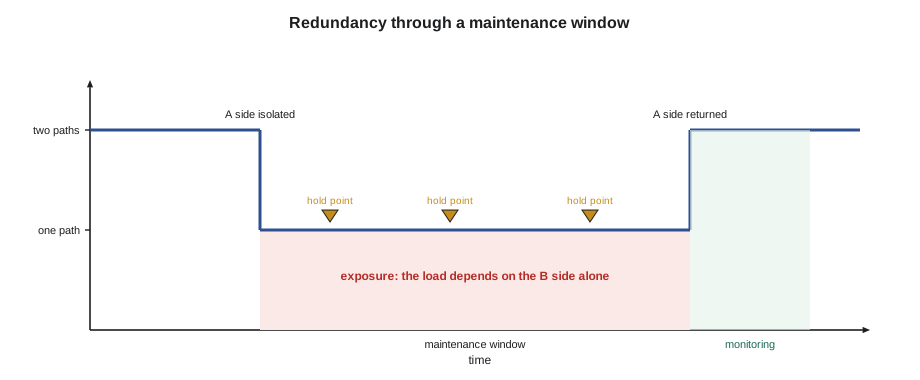
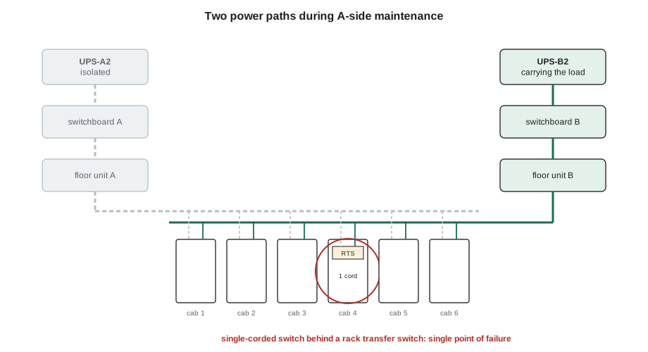
The promise has limits that every technician must understand. Concurrent maintainability covers planned maintenance of one thing at a time. It does not promise that the load survives a failure during maintenance; that is what the higher level of fault tolerance, Tier IV, adds. While UPS-A2 is out for maintenance, the cabinets in Hall A are running on the B side alone. If something on the B side fails during the window, every dual-corded cabinet in the hall loses both feeds. The facility is concurrently maintainable, but during the work it is at N, with no redundancy left.
The exposure window
The time a system spends at reduced redundancy is its exposure window. During it, the facility depends on equipment that would normally be backed up. Two things make the exposure smaller: making the window shorter and making failure of the remaining path less likely during it. Both are the work of planning.
A useful way to think about the risk is to estimate the chance that the remaining path fails during the window. For a path whose failures are random, with a known mean time between failures, the chance of at least one failure in a window of a few hours is small, but it grows with the length of the window. It also grows sharply if the remaining path is not in good condition, which is why the pre-checks below matter.
# Chance that the remaining path fails during a maintenance window (random failures)
import math
mtbf_path = 250_000          # hours, for the whole remaining path, illustrative
for window in (4, 8, 16, 48):
    p = 1 - math.exp(-window / mtbf_path)
    print(f"window {window:2} h: chance of a failure on the remaining path ~ 1 in {1 / p:,.0f}")
print()
# A remaining path with a known weakness (say an alarm left unresolved) is far worse
for mtbf in (250_000, 25_000):
    p = 1 - math.exp(-8 / mtbf)
print(f"8 h window, path MTBF {mtbf:>7,} h: ~ 1 in {1 / p:,.0f}")window 4 h: chance of a failure on the remaining path ~ 1 in 62,501 window 8 h: chance of a failure on the remaining path ~ 1 in 31,251 window 16 h: chance of a failure on the remaining path ~ 1 in 15,626 window 48 h: chance of a failure on the remaining path ~ 1 in 5,209 8 h window, path MTBF 250,000 h: ~ 1 in 31,251 8 h window, path MTBF 25,000 h: ~ 1 in 3,126
The numbers are illustrative, but the pattern is real. Halving the window halves the risk, and a remaining path with an unresolved problem can make the same window ten times riskier. Planning therefore aims at two things: short windows, and confirmation before the window opens that the path left carrying the load is healthy.
Before the window: confirm the other path
Before any equipment is isolated, the shift lead and the technician confirm the state of everything that will carry the load. Stonebridge's pre-checks for work that removes redundancy follow the same pattern for power, cooling and fire systems.
- The partner equipment is in service, in its normal mode and showing no alarms. For UPS work, the partner UPS is on inverter, not in bypass, with its batteries healthy and fully charged.
- Everything downstream on the remaining side is normal: switchboards, distribution units, busways and their breakers, all checked on the monitoring system and, for critical work, by a walk.
- Load on the remaining side is within what it can carry alone, with margin. In Hall A, the 2N planning limit of 40 percent per side in DCT-220 exists precisely so that one side can carry the whole hall.
- Single-corded equipment fed from the side being isolated has been identified, and its owners have agreed how it will be protected, usually through a rack transfer switch or a temporary move.
- No other work is planned on the remaining side, the generators serving it are available in automatic, and the weather forecast is acceptable.
- The tenants who must be notified have been notified, with the notice their contracts require.
These checks are written into the method of procedure as a hold point that must be signed before isolation begins. Dmitri's rule is that a pre-check found to be wrong stops the work until it is understood. Twice in his time at the campus a pre-check has found the partner UPS in bypass from a fault nobody had noticed, and both times the planned maintenance was postponed and the fault on the partner became the urgent job instead.
Single points of failure that remain
Even a well-designed concurrently maintainable facility has components that cannot be taken out without affecting someone. Technicians need to know where they are, because maintenance near them carries special risk.
- Single-corded equipment: a device with one power supply, fed from one side, depends entirely on that side. In Hall A, a customer's older network switch and a few appliances are single-corded and fed through small rack transfer switches, as DCT-220 Lesson 10 described. The transfer switch itself is a single point of failure for those devices.
- The last metre of each path: a cabinet's own power strips, a server's power supplies, a busway tap-off feeding one rack. These are part of one path only, and maintenance on them affects that path's load directly.
- Shared elements: a common chilled-water header between two loops, a single fuel tank shared by two generators, a fire suppression system covering a whole room. These are designed to be maintained in pieces or without interrupting protection, but the procedure must be followed exactly.
- Human single points: a valve that can be closed by mistake, a breaker that looks like its neighbour, a controller screen showing the wrong unit. Lesson 3's vendor example was one of these.
During the window
Once the pre-checks are signed, the work follows the method of procedure step by step, with the technician reading each step aloud, the vendor doing it and both confirming the result before the next. The method of procedure, as DCT-330 describes, has hold points at each change of state: before isolation, after isolation, before re-energizing, after return to service. At each hold point the shift lead confirms the plant is where the procedure says it should be.
Three habits keep the window short and safe. Do not start what cannot be finished: if the vendor's parts have not arrived or the forecast has changed, the window is postponed, not started in hope. Watch the remaining path, not only the work: during the window one technician watches the monitoring for the side carrying the load, because a problem there is the one that matters. And have the way back ready: each step of the procedure has a rollback, and the parts and people to carry it out are present before the step is taken.
Worked problem
A UPS window in Hall A
UPS-A2 is due for its annual internal inspection by the manufacturer's field engineers. The method of procedure transfers UPS-A2's load to its maintenance bypass, then isolates the UPS, leaving the A side on utility and generator power without battery protection, while the B side carries full protection.
Show solution
- The day before, Morgan confirms the vendor's team, parts and the tenant notices for Hall A. Dmitri confirms no other work is planned on the B side or on the Hall A generator block.
- At 08:00 the pre-check finds UPS-B2 on inverter with no alarms, its batteries at full charge and the B side carrying 47 percent of the hall's load. The A side's single-corded devices are behind their transfer switches, which are set to prefer the B side.
- At 08:20 the vendor transfers UPS-A2 to maintenance bypass under the procedure, Jamal confirming each breaker against the single-line diagram. The A side is now on unconditioned power.
- Through the morning, Roz watches the B side's monitoring and the weather. At 11:40 a short utility voltage dip shows in the logs; the A side rides through it on bypass and the B side's UPS carries its load without a transfer. The work continues.
- At 14:10 the vendor returns UPS-A2 to service, the procedure's return checks pass and the A side is back on inverter by 14:35. The window lasted six hours fifteen minutes against a plan of seven hours.
Answer: The work went to plan because the remaining path was confirmed healthy before it started and watched throughout. The voltage dip showed why: during the window, only the B side's UPS was protecting the load against the grid.
Cooling and mechanical work
The same principles apply to cooling, with some differences. Cooling usually has more redundant units than power, so taking one CRAH or one pump out of service reduces capacity rather than removing a whole path. But cooling systems have shared elements, such as headers, valves and control networks, and mistakes with valves can affect many units at once. Water does not stop flowing because a technician is surprised. Isolating a section of chilled-water pipe means closing valves in the right order, confirming the section is isolated, draining it safely and having absorbent materials and a leak response ready, as DCT-120 Lesson 10 described.
Cooling also has a time limit that power does not. A hall that loses some cooling capacity does not fail instantly; its temperature rises over minutes. That gives time to respond, but it also means that an unnoticed reduction in cooling during a window can turn into a hot hall an hour later. During mechanical work, a technician watches the hall's inlet temperatures and the remaining units' load, not only the unit being worked on.
After the window
Returning equipment to service is the riskiest part of many windows, because it is where maintenance-induced faults show up. The return steps are done as carefully as the isolation: checks that every tool and temporary connection has been removed, that covers and guards are back, that valves are in their normal positions, that controls are back in automatic and that alarms have cleared. Then the system is watched for a period, typically an hour for power equipment and a few hours for cooling, before the window is closed. The redundancy whiteboard is updated, the tenants are told the work is complete, and the vendor's report and the readings go into the CMMS.
# Return-to-service check: every item must be confirmed before the window closes
checks = {
    "all tools, meters and temporary leads removed": True,
    "covers, panels and guards refitted": True,
    "breakers and switches in normal positions (checked against single-line)": True,
    "controls back in automatic, no units left in maintenance mode": False,
    "alarms cleared at the panel and in monitoring": True,
    "partner and remaining path still normal": True,
    "observation period completed without new alarms": True,
}
open_items = [c for c, ok in checks.items() if not ok]
for c, ok in checks.items():
    print(("[x] " if ok else "[ ] ") + c)
print()
print("window can close" if not open_items else f"hold: {len(open_items)} item(s) open -> {open_items[0]}")[x] all tools, meters and temporary leads removed [x] covers, panels and guards refitted [x] breakers and switches in normal positions (checked against single-line) [ ] controls back in automatic, no units left in maintenance mode [x] alarms cleared at the panel and in monitoring [x] partner and remaining path still normal [x] observation period completed without new alarms hold: 1 item(s) open -> controls back in automatic, no units left in maintenance mode
The open item in this example is a classic: a unit left in maintenance mode at its controller after the work. It runs, but it will not restart automatically after a power interruption and will not answer the control system's call for more cooling. Many incidents in critical facilities begin with exactly this kind of leftover state, which is why the return checks are a list to tick, not a memory to trust.
Common mistakes
MistakeThinking concurrent maintainability means the load survives any failure during maintenance
InsteadDuring the window the system is at N; a failure on the remaining path can drop the load
MistakeStarting isolation without confirming the remaining path
InsteadDo the pre-checks and sign the hold point; a wrong pre-check stops the work
MistakeWatching only the equipment being worked on
InsteadHave someone watch the path carrying the load throughout the window
MistakeStarting a window that cannot be finished
InsteadPostpone if parts, people or weather are not right; do not start in hope
MistakeClosing the window as soon as the vendor finishes
InsteadComplete the return checks and an observation period, and update the whiteboard
Summary and key terms
- Concurrent maintainability lets any single component be maintained while the load runs, but during the work the system is at N.
- The exposure window is the time at reduced redundancy; shorter windows and healthy remaining paths reduce the risk.
- Pre-checks confirm the partner and the remaining path are normal, loads fit on one side and single-corded equipment is protected.
- Single-corded devices, last-metre equipment, shared elements and human mistakes remain single points of failure.
- During the window: follow the procedure, watch the remaining path and keep the way back ready.
- Return to service carefully, check off every item, observe, then update the whiteboard and tell the tenants.
- Concurrent maintainability
- The ability to maintain any component without interrupting the critical load.
- Fault tolerance
- The ability to survive a failure, including during maintenance, without affecting the load.
- Exposure window
- The time a system runs with reduced redundancy during maintenance.
- Single point of failure
- A component whose failure alone would interrupt the load or a part of it.
- Hold point
- A step in a procedure where work stops until a named person confirms the state.
- Maintenance bypass
- A path that carries load around a UPS so the UPS can be isolated.
- Rollback
- The planned way to return a system to its previous state if a step goes wrong.
Practice problems
Work each problem on paper first, then reveal the answer to check.
During A-side UPS maintenance in a 2N hall, what protects dual-corded cabinets?
Show answer
Only the B side; the hall is at N for the duration of the window.
Name three pre-checks before isolating a UPS.
Show answer
Any three of: partner UPS on inverter with no alarms, batteries charged, downstream equipment normal, load fits on one side, single-corded devices protected, no other work, generators available, tenants notified.
Why is a unit left in maintenance mode a risk after the window?
Show answer
It will not respond to the control system or restart automatically, so redundancy is quietly reduced.
What happens to the risk of a failure on the remaining path if the window doubles in length?
Show answer
It roughly doubles.
Lesson quiz · 5 questions
Score 60% or more to complete this lesson.
Create a free account to save your progress, take quizzes and earn a certificate.