
DCE-200 · Lesson 2 of 5 · 35 min
The power chain from grid to chip
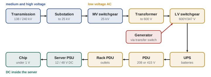
Electricity reaches a processor after a long journey. It leaves a power plant at a few thousand volts, is stepped up to hundreds of thousands of volts for transmission, stepped down several times on its way into the building, converted from AC to DC and back again inside a UPS, stepped down again for the racks, converted to DC in each server's power supply, and finally reduced to less than one volt at the chip. Every step costs a little energy, and every step is a place where something can fail.
This chapter follows that chain from the transmission grid to the processor: what each piece of equipment does, the voltages used in each part, how much current flows, where the backup power comes in, and where the losses occur. DCE-310 and DCE-340 cover the design of each part in detail.
From the transmission grid
Large data centres connect directly to the transmission system. In Alberta, transmission lines operate mainly at 138 kV and 240 kV, with a 500 kV backbone; other provinces use similar levels (Ontario, for example, uses 115 kV, 230 kV and 500 kV). A campus of 100 MW or more usually needs its own substation, built by the transmission owner or by the developer to the utility's standards, where transformers step the voltage down to a medium voltage, commonly 25 kV in Alberta.
Why such high voltages? The power carried by a line is proportional to voltage times current, but the heat lost in the conductors is proportional to the current squared times the resistance (\(P_\text{loss} = I^2R\)). Raising the voltage tenfold cuts the current tenfold for the same power, and the losses a hundredfold. High voltage is how power travels efficiently; low voltage is how it is used safely.
Reliability starts at the connection. Many data centres ask for two utility feeds from different substations or different transmission lines, so that a single line outage does not reach the building. Whether that is possible, how long it takes and who pays for it are among the first questions in any project (Lesson 5).
Three-phase power
Almost all power in a data centre is three-phase alternating current: three conductors carry sinusoidal voltages 120° apart. Three-phase delivers power smoothly and uses less conductor material than single-phase for the same power. For a balanced three-phase load,
where \(V_L\) is the line-to-line voltage, \(I\) the line current and pf the power factor (close to 1 for modern IT equipment, whose power supplies correct it). Without the power factor, \(S = \sqrt{3} V_L I\) is the apparent power in volt-amperes (VA or kVA), the quantity transformers and UPS systems are rated in.
In a "wye" (star) system, each phase can also be connected to the neutral, giving a lower voltage \(V_L/\sqrt{3}\). That is where the familiar pairs of numbers come from:
- 600Y/347 V: the standard Canadian low-voltage system for commercial and industrial buildings (600 V line to line, 347 V line to neutral, used for lighting).
- 208Y/120 V: used for receptacles and much IT equipment in North America.
- 415Y/240 V: increasingly used for racks, because 240 V line to neutral suits IT power supplies directly while 415 V three-phase carries twice the power of 208 V on the same current.
Worked problem
Current at different voltages
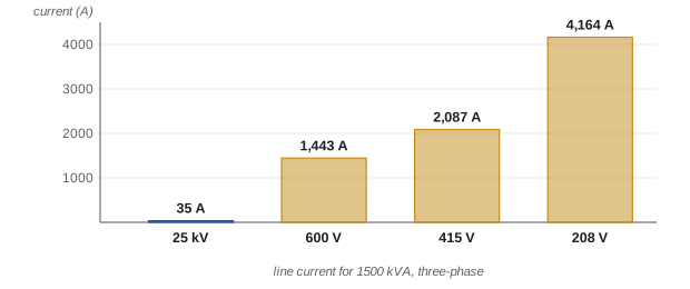
A 1500 kVA transformer feeds a data hall. Find the full-load current on its secondary if the secondary is 600 V, and compare with 415 V and 208 V.
Show solution
- \(I = S/(\sqrt{3}V_L)\).
- At 600 V: \(I = 1{,}500{,}000/(1.732 \times 600) = 1443\) A.
- At 415 V: 2087 A. At 208 V: 4164 A.
Answer: About 1440 A at 600 V, 2090 A at 415 V and 4160 A at 208 V. Lower voltage means more current, which means larger conductors, larger breakers and more heat loss. That is why power is distributed at 600 V as far as possible and stepped down close to the load
Inside the building: switchgear and transformers
Medium-voltage power (for example 25 kV) enters the building or the yard through medium-voltage switchgear: an assembly of circuit breakers, protective relays and metering that can isolate faults and switch circuits. It feeds unit substations, each a transformer of typically 2 to 3.5 MVA that steps the voltage down to 600 V, bolted to low-voltage switchgear that distributes power to UPS systems and mechanical equipment.
Data centre electrical systems are usually divided into identical blocks (say, 2 or 3 MW each), each with its own transformer, generator and UPS. Blocks make it easy to build in phases, to repeat a proven design, and to arrange redundancy (Lesson 4).
Every point in the system must be protected: a short circuit can release enormous energy. Circuit breakers and fuses must interrupt the available fault current, and they must be coordinated so that the device nearest a fault trips first, leaving the rest of the system running. An arc flash, the explosive release of energy when current jumps through air between conductors, can kill workers; arc flash studies label every panel with its hazard so that workers wear the right protection.
Backup power: UPS and generators
When the utility fails, two systems take over.
Uninterruptible power supply (UPS)
A UPS sits between the switchgear and the IT load. The most common type in data centres, the double-conversion UPS, continuously converts incoming AC to DC (charging the batteries) and back to clean AC for the load. If the input fails, the batteries keep the output going with no interruption at all. The UPS also filters out voltage sags, spikes and frequency changes from the grid.
The batteries only need to last until the generators start and take the load, typically under a minute, but designers usually provide 5 to 10 minutes at full load for margin. Valve-regulated lead-acid batteries were the norm; lithium-ion batteries now dominate new installations because they are smaller, lighter and last longer, though they need careful fire protection (DCE-440).
Worked problem
Battery energy for ride-through
A UPS supports 1 MW of IT load. The design calls for 5 minutes of battery runtime at full load, and the UPS inverter is 95% efficient. How much usable battery energy is needed?
Show solution
- Energy delivered to the load = 1000 kW × (5/60) h = 83.3 kWh.
- The batteries must supply the inverter's losses too: 83.3 ÷ 0.95 = 87.7 kWh.
Answer: About 88 kWh of usable energy. Battery vendors then add allowances for ageing and temperature, so the installed capacity is larger
Generators
Standby generators, usually diesel engines driving alternators of 2 to 3 MW each, carry the load through long outages. When the utility fails, the generators start, reach speed and voltage in about 10 seconds, and automatic transfer switches (or paralleling switchgear) move the load from the utility to the generators. When the utility returns and has been stable for some minutes, the load is transferred back.
Fuel is stored on site, typically for 24 to 72 hours at full load, with contracts for refuelling during long emergencies. Some operators now run generators on renewable diesel; others are installing natural gas engines, turbines or fuel cells that can run continuously, not just in emergencies (DCE-420).
Worked problem
Fuel for a long outage
A 2.5 MW diesel generator burns about 0.27 L of fuel per kWh at full load. How much fuel does it need for 48 hours at full load?
Show solution
- Fuel rate = 2500 kW × 0.27 L/kWh = 675 L/h.
- For 48 h: 675 × 48 = 32,400 L.
Answer: About 32,400 L (32.4 m³) per generator. A 20 MW facility with 8 such generators would store about 260,000 L of diesel, which brings fire code, spill containment and environmental permitting requirements
Generators are tested regularly under load, because a generator that has not been exercised is the most likely piece of equipment to fail on the day it is needed.
To the rack
From the UPS, power flows to power distribution units (PDUs) in or near the white space. A PDU is a cabinet containing a transformer (where needed), a panelboard of breakers and monitoring. Each PDU feeds branch circuits to the racks, often through overhead busway: a prefabricated enclosed bar with tap-off boxes that can be plugged in wherever a rack needs power. Inside each rack, rack PDUs (power strips) distribute power to the individual pieces of equipment and usually meter each outlet.
Most IT equipment has two power supplies, fed from two different rack PDUs on two different upstream paths (often called A and B). If one path fails or is shut down for maintenance, the other carries the whole load.
Worked problem
How much power can a rack circuit carry?
A rack is fed by a 208 V three-phase circuit protected by a 60 A breaker. IT load is continuous, so the Canadian Electrical Code limits the continuous load on a standard breaker to 80% of its rating. What power can the circuit deliver? What if it were 415 V?
Show solution
- Usable current = 0.8 × 60 = 48 A.
- At 208 V: \(\sqrt{3} \times 208 \times 48 = 17{,}300\) VA ≈ 17.3 kVA.
- At 415 V: \(\sqrt{3} \times 415 \times 48 = 34{,}500\) VA ≈ 34.5 kVA.
Answer: About 17 kW at 208 V and 34.5 kW at 415 V (power factor near 1). Doubling the voltage doubles the power per circuit, which is one reason high-density racks use 415 V. An AI rack drawing 120 kW needs several such circuits or a dedicated high-current feed
Inside the server
The server's power supply unit (PSU) converts AC to low-voltage DC, traditionally 12 V and increasingly 48 V in high-power systems. On the motherboard, voltage regulator modules (VRMs) convert that to the roughly 0.7 to 1 V a modern processor core runs on. At these voltages the currents are enormous: a GPU drawing 1000 W at 0.8 V draws about 1250 A, which is why the regulators sit right next to the chip.
Each conversion loses energy. That has led the industry toward fewer conversions. One direction is 48 V distribution inside the rack, from a shared power shelf. Another is high-voltage DC: NVIDIA and partners have published designs for 800 V DC power to future AI racks approaching 1 MW, removing several AC-to-DC conversions and much of the copper that low-voltage distribution would need.
Where the energy goes
Because each stage is efficient but not perfect, the losses multiply.
Worked problem
Efficiency of the chain
Electricity passes through a medium-voltage transformer (98.5% efficient), a double-conversion UPS (96%), a PDU transformer (98%) and server power supplies (94%). For 10 MW delivered to the server electronics, how much must enter the chain, and how much is lost as heat?
Show solution
- Overall efficiency = 0.985 × 0.96 × 0.98 × 0.94 = 0.871.
- Input = 10 ÷ 0.871 = 11.48 MW.
- Losses = 11.48 − 10 = 1.48 MW.
Answer: About 11.5 MW enters and 1.5 MW is lost, all as heat that the cooling system must also remove. Choosing a UPS with an efficient operating mode or eliminating a transformer stage can save hundreds of kilowatts
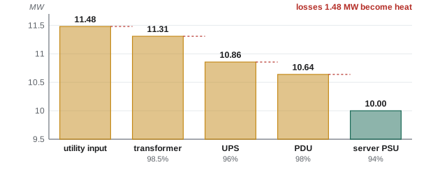
Note that in the PUE of Lesson 1, losses before the IT equipment (transformers, UPS, PDUs) count as facility overhead, while losses in server power supplies count as IT energy, because they are measured inside the IT equipment.
Codes and safety
Every part of the installation must meet the Canadian Electrical Code, Part I (CSA C22.1) as adopted and amended by the province, and equipment must be certified to Canadian standards (look for the CSA, cUL or other accredited certification mark). Medium-voltage and high-voltage work, the utility interface, generator installations and battery rooms each bring additional rules. Workers follow CSA Z462, Workplace Electrical Safety, for arc flash and shock protection. Electrical permits and inspections are issued by the provincial or municipal electrical inspection authority.
Common mistakes
MistakeConfusing kVA with kW.
InsteadkVA is apparent power (volts × amperes); kW is real power. kW = kVA × power factor. Transformers and UPS systems are rated in kVA.
MistakeUsing \(P = V I\) for a three-phase circuit.
InsteadFor three-phase, \(P = \sqrt{3}\, V_L I\, \text{pf}\), with the line-to-line voltage.
MistakeLoading a breaker to 100% of its rating with continuous IT load.
InsteadStandard breakers carry continuous load only up to 80% of their rating.
MistakeAssuming the UPS batteries carry the load through an outage.
InsteadBatteries bridge the few seconds to minutes until generators take over. Long outages are carried by generators and fuel.
MistakeForgetting that electrical losses become heat.
InsteadLosses in transformers, UPS systems and PDUs add to the cooling load in the rooms where that equipment sits.
Summary and key terms
- Power travels at high voltage to keep current and \(I^2R\) losses low, and is stepped down close to where it is used.
- Typical chain in Canada: transmission (138 to 500 kV) → substation → medium voltage (often 25 kV) → unit substations at 600Y/347 V → UPS → PDUs at 208Y/120 V or 415Y/240 V → rack PDUs → server power supplies (12 or 48 V DC) → regulators (under 1 V).
- Three-phase power: \(P = \sqrt{3} V_L I\,\text{pf}\). Apparent power in kVA, real power in kW.
- A double-conversion UPS with batteries carries the load seamlessly for minutes; diesel generators start in about 10 seconds and carry long outages from stored fuel.
- IT equipment usually has two power supplies on independent A and B paths.
- Continuous loads are limited to 80% of a standard breaker's rating.
- Efficiencies multiply: a chain of four 94–98.5% stages delivers about 87% of the input.
- Transmission
- High-voltage lines (above about 69 kV) that carry bulk power between generating stations and substations.
- Medium voltage
- Distribution voltages from about 1 kV to 35 kV, used to carry power around a campus.
- Substation
- A facility with transformers and switchgear that changes voltage and switches circuits.
- Switchgear
- An assembly of circuit breakers, relays and metering that controls and protects electrical circuits.
- Unit substation
- A transformer close-coupled to medium-voltage and low-voltage switchgear.
- Apparent power (kVA)
- The product of voltage and current in an AC circuit; equals real power divided by power factor.
- Power factor
- The ratio of real power (kW) to apparent power (kVA).
- UPS
- Uninterruptible power supply: equipment that conditions power and uses stored energy to carry the load without interruption when the input fails.
- Automatic transfer switch (ATS)
- A switch that moves a load between the utility and a generator automatically.
- PDU
- Power distribution unit: a cabinet that distributes power to racks, often with a step-down transformer.
- Busway
- Prefabricated enclosed busbars with plug-in tap-off boxes, used for overhead power distribution to racks.
- Arc flash
- The explosive release of energy from an electric arc through air between conductors.
- Power supply unit (PSU)
- The converter in a server that changes AC input into low-voltage DC.
Practice problems
Work each problem on paper first, then reveal the answer to check.
A three-phase load draws 200 A at 480 V with a power factor of 0.95. Find its apparent and real power.
Show answer
S = 1.732 × 480 × 200 = 166.3 kVA; P = 0.95 × 166.3 = 158 kW.
A 2500 kVA transformer has a 600 V secondary. What is its full-load secondary current?
Show answer
I = 2,500,000 ÷ (1.732 × 600) = 2406 A.
What is the line-to-neutral voltage of a 415 V wye system?
Show answer
415 ÷ 1.732 = 240 V.
A rack is fed by two 208 V three-phase 30 A circuits (A and B). What is the most IT load it should carry so that either circuit alone can support it?
Show answer
One circuit: 0.8 × 30 = 24 A; 1.732 × 208 × 24 = 8.6 kW. The rack should be limited to about 8.6 kW so either feed can carry it all.
If conductor current is halved by doubling the voltage, by what factor do the \(I^2R\) losses change?
Show answer
They fall to one quarter.
A 500 kW UPS must provide 8 minutes of runtime at full load with a 96% efficient inverter. Find the usable battery energy.
Show answer
500 × 8/60 = 66.7 kWh; ÷ 0.96 = 69.4 kWh.
Eight 3 MW generators burn 0.26 L/kWh at full load. How much fuel do they need for 24 hours at full load?
Show answer
8 × 3000 × 0.26 = 6240 L/h; × 24 = 149,760 L (about 150 m³).
A UPS is 94% efficient at the operating point. At 2 MW output, how much heat does it produce?
Show answer
Input = 2 ÷ 0.94 = 2.128 MW; heat = 128 kW.
A chain has efficiencies 99%, 97%, 99% and 95%. What fraction of the input reaches the electronics?
Show answer
0.99 × 0.97 × 0.99 × 0.95 = 0.903, about 90%.
Why do servers usually have two power supplies?
Show answer
So each can be fed from a separate path (A and B). If one path fails or is taken out for maintenance, the other supply carries the whole load.
Lesson quiz · 5 questions
Score 60% or more to complete this lesson.
Create a free account to save your progress, take quizzes and earn a certificate.