
CON-250 · Lesson 12 of 12 · 26 min
Machine control, site technology and the site plan
For most of the history of earthwork, operators built grades by reading stakes, and grade checkers walked behind the machines with a level and a rod. Today, on many sites, the design model is loaded directly into the machine, and the operator sees the cut or fill under the blade or bucket on a screen in the cab. Drones measure progress weekly, compaction rollers map the stiffness of each lift, and telematics report every machine's hours and fuel. This final lesson explains machine guidance and machine control, the data workflow that feeds them, the checks that keep them honest and the wider set of site technologies. It ends by bringing the whole course together in a site layout and earthwork plan.
Machine guidance and machine control
There are two levels of automation. Machine guidance shows the operator where the blade or bucket is relative to the design, using lights or a screen, and the operator controls the machine. Machine control goes further: the system drives the hydraulics to hold the blade on grade automatically, while the operator steers and manages the work. Excavators usually use guidance or semi-automatic control of the bucket; dozers and graders commonly use full automatic blade control.
Systems also differ by how they know where the machine is.
- 2D systems use a rotating laser as the reference plane, with a receiver on the blade mast. They are simple and accurate for flat pads and single slopes, but cannot follow complex surfaces.
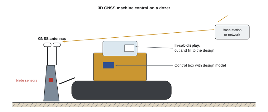
- 3D GNSS systems use one or two GNSS receivers on the machine and corrections from a base or network, combined with tilt and angle sensors on the blade, boom and stick, to know the cutting edge's position in three dimensions. They follow any design surface and are the most common systems for earthwork.
- 3D total station systems use a robotic total station that tracks a prism on the machine, giving millimetre-level accuracy for fine grading of base courses, curbs and pavements, where GNSS vertical accuracy is not good enough.
| System | Typical vertical accuracy | Typical use |
|---|---|---|
| Visual grading from stakes | 30 to 50 mm, operator dependent | Small jobs, rough grading |
| 2D laser control | 5 to 15 mm | Building pads, sports fields, single-slope areas |
| 3D GNSS control | 20 to 30 mm | Mass earthwork, subgrade, ditches, slopes |
| 3D total station control | 3 to 10 mm | Fine grading of base, curb and paving |
Benefits and limits
Contractors adopt machine control because it reduces staking and re-staking, cuts the number of passes needed to reach grade, reduces over-excavation and wasted material, lets machines work at night or in conditions where stakes are hard to see, and reduces the number of people on foot near moving equipment. Many contractors report productivity gains of tens of per cent on grading work, and large savings in granular materials from not overbuilding the base.
The system is only as good as its data and its setup. A machine with the wrong design file, a bad calibration, an out-of-date site localization, a bent blade sensor or a GNSS float solution will build the wrong grade with complete confidence. Machine control does not remove the need for survey; it moves the surveyor's work from setting stakes to preparing data and checking results.
The data workflow
Machine control depends on a chain of digital information, and every link must be correct.
- Existing surface: the topographic survey, drone or lidar surface, with breaklines, tied to project control.
- Design model: the designer's grading surfaces, alignments and corridors, ideally as 3D files rather than drawings.
- Data preparation: a surveyor or data prep specialist converts the design into machine-ready surfaces, such as subgrade surfaces offset below finished grade by the pavement structure, separate surfaces for topsoil stripping, trenches and pads, and splits large models into manageable files.
- Site calibration and control: the same localization file is loaded on every rover and every machine.
- Distribution: files are sent to machines, increasingly over the cloud, with version control so that superseded files are removed.
- As-built and quantities: machines and rovers record as-built points and surfaces, which feed progress quantities and final records.
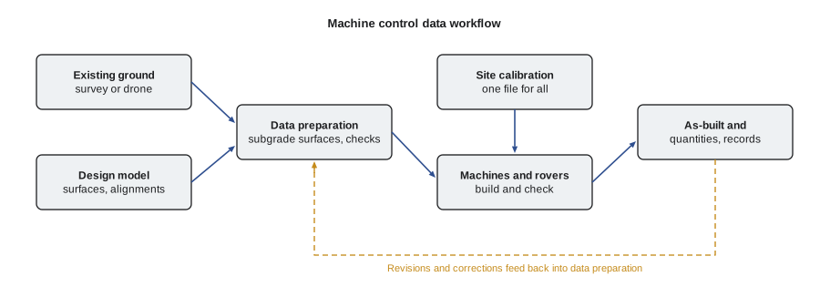
Data preparation is where many problems start. Typical errors include building to finished grade instead of subgrade, missing a design revision, mismatched units or vertical datums, surfaces with spikes or holes where the design was incomplete, and the wrong pavement thickness applied to part of a site. A good practice is for the data preparer to produce a short report with each file: what surfaces it contains, which design revision it reflects, the offsets applied, and a few check elevations at known points.
Checking machine-built grades
Every machine control site needs a routine of checks.
- At the start of each shift, the operator checks the machine on a known point or a check plate: a surveyed spot where the blade edge or bucket teeth can be set to compare the displayed elevation with the known value.
- A grade checker with a GNSS rover or total station checks the work against the design surface regularly and records the results.
- Blade and bucket sensors are recalibrated after any repair, bucket change or impact.
- Before the next layer is placed, the surface is checked against tolerance, and the results are recorded as part of quality control.
Worked problem
Check on a known point
A dozer's display shows the blade edge at 100.318 m when set on a check plate surveyed at 100.285 m. The site allows 20 mm. What should happen?
Show solution
- Difference = 100.318 − 100.285 = 0.033 m = 33 mm, which exceeds 20 mm.
- The machine would build grades about 33 mm low, because it thinks the blade is higher than it is.
- Stop grading, check the GNSS fix and calibration file, the antenna and blade measurements, and recalibrate the sensors before continuing.
Answer: Stop: the 33 mm error exceeds the tolerance.
Intelligent compaction and payload systems
Intelligent compaction rollers measure the response of the drum as it vibrates, producing a stiffness value for each location, and map it with GNSS. Combined with pass counts and temperature for asphalt, these maps show the whole area rather than the few spot tests from a density gauge, and they help find soft spots before the next layer is placed. Agencies increasingly specify intelligent compaction for embankments and paving, while still using conventional density tests for acceptance.
Payload systems on loaders, excavators and trucks weigh each bucket or load. They reduce overloading and underloading, improve the accuracy of production records and support tonnage-based payments. On excavators, they can show the operator the remaining payload needed to fill a truck exactly.
Telematics and connected sites
Most modern machines report their location, engine hours, idle time, fuel use, fault codes and maintenance status through telematics. An industry standard, ISO 15143-3 (often called the AEMP 2.0 standard), lets contractors bring data from mixed fleets into one system. Telematics help schedule maintenance, reduce idling, detect theft and confirm hours billed by rental companies or subcontractors.
Cloud platforms now link design files, machine control, survey and drone data, so that a project team can see the current surface, the design and the cut and fill remaining from an office or a phone. Weekly drone flights and machine as-built data allow earthwork quantities and progress payments to be based on measured surfaces rather than estimates.
Safety technology and automation
Technology is also changing equipment safety. Proximity detection systems use radio tags worn by workers, radar or cameras with machine learning to warn operators, or stop machines, when a person enters a danger zone. Surround-view cameras remove many blind spots. Geofencing can limit an excavator's swing or height near power lines or traffic. Remote control lets operators run machines from a safe distance in hazardous areas such as unstable slopes or demolition.
Autonomous and semi-autonomous machines, already common in large mines, are appearing on construction sites for repetitive tasks such as compaction, trenching for solar farms and dozing on large earthwork projects. Electric and hybrid compact equipment is growing quickly, driven by urban noise and emissions limits. These changes increase the need for clear site rules, exclusion zones and competent supervision rather than reducing it.
Capstone: a site layout and earthwork plan
A construction manager preparing for the site works on a commercial project brings together everything in this course. The plan typically covers the following elements, each linked to a lesson.
| Plan element | What it contains | Lessons |
|---|---|---|
| Survey and control plan | Datum, coordinate system, control points, benchmarks, protection, check schedule, who sets what | 1 to 4 |
| Layout plan | Building control, gridlines, offsets, anchor bolts, transfer up the building, tolerances, layout log | 5 and 6 |
| Grading and utilities layout | Profiles, grade staking or machine control, pipe grades and inverts | 7 |
| Earthwork quantities | Cut, fill, topsoil, unsuitable material, swell and shrinkage | 8 |
| Balance and haul plan | Mass haul or site balance, stockpiles, haul routes, import and export, excess soil rules | 9 |
| Equipment plan | Machines selected, fleet balance, productivity, schedule | 10 and 11 |
| Cost estimate | Owning and operating costs, unit costs, indirect costs | 11 |
| Technology and quality plan | Machine control data, checks, compaction testing, as-builts and records | 12 |
Worked problem
Capstone estimate for a site
A commercial site has 9,000 BCM of usable cut and 6,800 CCM of fill, with 15 per cent shrinkage. Topsoil 200 mm deep is stripped from 1.5 ha and stockpiled. The internal haul is about 250 m. The spread from Lesson 11 (excavator and 3 trucks) produces 197 BCM/h at $617/h. Plan the earthwork.
Show solution
- Fill in bank volume = 6,800 ÷ 0.85 = 8,000 BCM. Surplus = 9,000 − 8,000 = 1,000 BCM, to be used in berms or exported under the excess soil rules.
- Topsoil = 15,000 m² × 0.200 = 3,000 BCM, about 3,600 LCM in the stockpile at 20 per cent swell; plan its location away from control points and haul routes.
- Hours to move 8,000 BCM on site = 8,000 ÷ 197 = 41 hours, about 5 to 6 working days at 8 hours, before weather allowance.
- Direct cost of the cut-to-fill operation = 41 × 617 ≈ $25,300, or $3.13/BCM; add spreading and compaction, grading, survey, testing, haul road maintenance and the cost of exporting or reusing the 1,000 BCM surplus.
- Control and checks: four primary control points outside the work, one site calibration for all rovers and machines, daily check plates, and weekly drone surveys for progress quantities.
Answer: About 41 hours of excavate-and-haul at about $3.13/BCM, with 1,000 BCM surplus and 3,000 BCM of topsoil to manage.
A plan like this is never final. The construction manager updates it as the work proceeds: comparing surveyed progress with the schedule, adjusting the fleet, revising the balance when unsuitable material appears, and recording what was built. The habits from this course, which are to check against control, state the condition of every quantity, balance the fleet and track actual production, are what keep the plan connected to reality.
Professional practice
Surveying and site technology are fields where small errors propagate into large consequences, and where clear responsibility matters. Contracts should say who provides control, who lays out what, who prepares machine control data and who checks it. Licensed surveyors must be engaged for boundary work and for any certification the authorities require. Construction managers should insist on documented control, version-controlled design files, daily checks and recorded results, and should be willing to stop the work when a check fails. A day lost to re-checking control is cheap compared with a building in the wrong place.
Common mistakes
MistakeAssuming machine control eliminates the need for survey.
InsteadSurvey work shifts to data preparation, calibration and checking; it is still essential.
MistakeLoading a design file without a data preparation report.
InsteadRequire each file to state its surfaces, design revision, offsets and check elevations.
MistakeBuilding to finished grade instead of subgrade.
InsteadConfirm which surface the machine is using and that the pavement or slab structure has been subtracted.
MistakeSkipping the daily check plate.
InsteadCheck every machine on a known point at the start of each shift and after any repair or bucket change.
MistakeLetting old design files stay on machines.
InsteadUse version control and remove superseded files from every machine and rover.
MistakeRelying on proximity detection instead of exclusion zones.
InsteadUse technology as an additional layer, not a replacement for planned separation and supervision.
Summary and key terms
- Machine guidance shows the operator the grade; machine control drives the blade automatically.
- 2D laser systems suit flat or single-slope work; 3D GNSS suits earthwork; 3D total station suits fine grading.
- Machine control depends on a chain of data: existing surface, design model, data preparation, calibration and distribution.
- Data preparation errors, such as finished grade instead of subgrade, are a common cause of wrong grades.
- Daily check plates, grade checking and sensor calibration keep machine control honest.
- Intelligent compaction, payload systems, telematics and drones provide measured data on progress and quality.
- A site layout and earthwork plan brings together control, layout, quantities, balance, equipment, cost and quality.
- Machine guidance
- A system that shows the operator the position of the blade or bucket relative to the design.
- Machine control
- A system that automatically controls the blade or bucket to follow the design.
- 2D laser control
- Machine control using a rotating laser plane as the reference.
- 3D GNSS control
- Machine control using GNSS and sensors to position the cutting edge in three dimensions.
- Data preparation
- Converting design information into machine-ready surfaces and files.
- Check plate
- A surveyed point used to verify a machine's displayed elevation.
- Intelligent compaction
- Roller systems that measure and map material stiffness and passes.
- Payload system
- A system that weighs each bucket or truck load.
- Telematics
- Remote reporting of machine location, hours, fuel and condition.
- Proximity detection
- Technology that warns of, or prevents, contact between machines and people.
Practice problems
Work each problem on paper first, then reveal the answer to check.
What is the difference between machine guidance and machine control?
Show answer
Guidance shows the operator the grade; control moves the hydraulics automatically to hold grade.
Which machine control system is best for fine grading a granular base under pavement?
Show answer
A 3D total station system, because of its millimetre-level vertical accuracy.
Name three items a data preparation report should state.
Show answer
Surfaces included, design revision, offsets applied (such as pavement thickness), and check elevations.
A machine reads 52.410 m on a check plate surveyed at 52.398 m. The tolerance is 20 mm. Is it acceptable?
Show answer
Yes: the difference is 12 mm.
Why can intelligent compaction find problems that spot density tests miss?
Show answer
It maps stiffness over the whole area rather than at a few test locations.
Give two uses of telematics data.
Show answer
Maintenance scheduling, reducing idle time, theft detection, verifying hours, tracking fuel.
A site has 5,000 BCM of cut and 4,675 CCM of fill with 15 per cent shrinkage. Is there a surplus or a shortfall?
Show answer
Fill needs 4,675 ÷ 0.85 = 5,500 BCM, so there is a 500 BCM shortfall to import.
Who should establish legal boundaries on a project with machine control?
Show answer
A licensed land surveyor; technology does not change that requirement.
Lesson quiz · 5 questions
Score 60% or more to complete this lesson.
Create a free account to save your progress, take quizzes and earn a certificate.