
CON-100 · Lesson 5 of 12 · 25 min
Design phases and construction documents
Before anything can be built, it must be designed and described in documents that a contractor can price and build from. The design process moves from broad ideas to precise instructions, and at each stage the owner, designers and often the contractor make decisions that fix more of the project. The resulting construction documents, drawings and specifications, together with the contract, define what the contractor must deliver. Construction managers spend much of their working lives reading, questioning and interpreting these documents. This lesson explains the design phases, the kinds of drawings and specifications produced, how they are organized, how estimates and schedules develop alongside the design, and how documents are used during construction.
The design phases
Building design typically progresses through a sequence of phases, defined in the standard agreements between owners and architects:
- Pre-design or programming: establishing what the owner needs, such as the number and size of spaces, their relationships, performance requirements, budget and schedule. The result is the functional program or brief.
- Schematic design: exploring and choosing an overall concept, including site layout, massing, floor plans, main structural and mechanical approaches and appearance. Drawings are simple, and the cost estimate is broad.
- Design development: developing the chosen scheme in detail, fixing dimensions, structural systems, building envelope, mechanical and electrical systems and major materials. Outline specifications are written, and the estimate becomes more detailed.
- Construction documents: preparing the complete, coordinated drawings and specifications needed to obtain permits, tender and build the project.
- Bidding or tendering and contract award, followed by construction administration.
Infrastructure projects follow similar steps, often described as preliminary design, detailed design and tender documents, with percentages such as 30 %, 60 %, 90 % and 100 % design used to mark progress.
| Phase | Typical outputs | Estimate class (approximate) |
|---|---|---|
| Programming | Functional program, space list, budget | Order of magnitude |
| Schematic design | Site plan, floor plans, massing, outline systems | Class D or concept |
| Design development | Detailed plans, sections, systems design, outline specifications | Class C or B |
| Construction documents | Complete drawings and specifications | Class A or pre-tender |
Estimates through design
Cost estimates are prepared at each design phase, becoming more accurate as more is known. Early estimates rely on costs per square metre or square foot for similar buildings, adjusted for location, time and quality; later estimates use elemental costs, such as costs for foundations, structure, envelope and systems; and pre-tender estimates use detailed quantities and unit prices (CON-200).
In Canada, the Canadian Institute of Quantity Surveyors (CIQS) and the Royal Architectural Institute of Canada describe estimate classes from Class D (concept, accuracy roughly ±20–25 %) through Class C and Class B to Class A (pre-tender, roughly ±5–10 %), and elemental estimating using a standard element format is widely used by quantity surveyors and public owners.
Estimates at each stage are compared with the budget. If the estimate exceeds the budget, the owner must reduce scope, change systems or materials, increase the budget, or accept risk; finding this out early, rather than when bids arrive, is one of the main reasons owners involve cost consultants or construction managers during design.
Worked problem
An early square-metre estimate
An owner plans a 6,500 square metre elementary school. Recent comparable schools in the region cost about $4,800 per square metre for construction. Construction is expected to start in two years, and cost escalation is forecast at 4 % per year. Estimate the construction cost.
Show solution
- Base cost: \(6{,}500 \times 4{,}800 = 31.2\) million dollars.
- Escalation over two years: \(1.04^2 = 1.0816\).
- Escalated cost: \(31.2 \times 1.0816 \approx 33.7\) million dollars.
- At concept stage, a design and pricing contingency of perhaps 10–15 % would usually be added, giving roughly $37 to $39 million.
Answer: About $33.7 million before contingency, or roughly $37–39 million with a concept-stage contingency.
Construction drawings
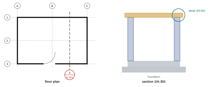
Construction drawings show what is to be built and where. A set of building drawings is organized by discipline, each with its own sheet prefix, typically G for general, C for civil, L for landscape, A for architectural, S for structural, M for mechanical, P for plumbing, FP for fire protection, E for electrical and T for telecommunications. Within each discipline, drawing types include:
- Plans: horizontal views, such as site plans, foundation plans, floor plans, reflected ceiling plans and roof plans.
- Elevations: vertical views of the outside or inside faces of the building.
- Sections: vertical cuts through the building or parts of it, showing how elements fit together.
- Details: enlarged drawings of specific connections and assemblies.
- Schedules: tables listing doors, windows, finishes, equipment, beams or fixtures with their properties.
Drawings use standard scales, symbols, abbreviations and conventions, and they reference each other through grid lines, section marks and detail callouts. CON-120 teaches how to read them in depth.
Specifications
Specifications describe the quality of materials, products and workmanship, the standards to be met, and the procedures for submittals, testing, installation and closeout. Drawings show quantity, location and arrangement; specifications show quality and requirements. Specifications are organized in a standard format so that information can be found consistently: in both Canada and the United States, most building specifications follow MasterFormat, published by the Construction Specifications Institute and Construction Specifications Canada, which organizes work into numbered divisions, such as Division 03 Concrete, Division 05 Metals, Division 08 Openings, Division 23 HVAC and Division 26 Electrical, and each specification section into three parts: General, Products and Execution. Division 01 General Requirements covers administrative and procedural matters for the whole project, such as submittals, quality control, temporary facilities and closeout, and it is one of the most important sections for the contractor.
| MasterFormat division | Content |
|---|---|
| 01 General Requirements | Administration, submittals, quality, temporary facilities, closeout |
| 03 Concrete | Formwork, reinforcing, cast-in-place and precast concrete |
| 05 Metals | Structural steel, steel joists and deck, metal fabrications |
| 07 Thermal and Moisture Protection | Insulation, air and vapour barriers, roofing, sealants |
| 08 Openings | Doors, frames, windows, hardware, glazing |
| 09 Finishes | Drywall, ceilings, flooring, painting |
| 22 Plumbing / 23 HVAC | Plumbing systems; heating, ventilating and air conditioning |
| 26 Electrical | Power, lighting and electrical systems |
The contract documents
The drawings and specifications form part of the contract documents, together with the agreement between owner and contractor, the general and supplementary conditions of the contract, and addenda issued during tendering. The contract usually sets out an order of precedence for resolving conflicts between documents, such as specifications prevailing over drawings, or larger-scale drawings over smaller-scale ones, and requires the contractor to report discrepancies it finds. Documents are complementary: what is required by one is as binding as if required by all. Understanding the contract documents as a whole, not just the drawings, is essential for estimating, buying out and building the work correctly.
Building information modelling
Increasingly, designs are produced as building information models (BIM): three-dimensional digital models containing information about each element, from which drawings, quantities and schedules can be generated. BIM allows designers and contractors to coordinate disciplines and detect clashes, such as ducts running through beams, before construction; to visualize sequences; and to hand over information-rich models for facility management. Contract documents may still be the two-dimensional drawings and specifications, with the model provided for reference, or the model itself may be contractual, depending on the project's BIM execution plan. CON-260 explores BIM and digital tools.
Documents during construction
During construction, documents continue to evolve. Addenda modify tender documents before bids close. Requests for information (RFIs) ask designers to clarify ambiguities. Shop drawings and submittals, prepared by subcontractors and suppliers, show exactly how products will be fabricated and installed, and are reviewed by the designers for general conformance. Supplemental instructions, change directives and change orders modify the work. Field reports, inspection reports and test results record quality. At the end, as-built or record drawings show what was actually built. Managing this flow of documents accurately and promptly is one of the core functions of a construction manager (CON-375).
Coordination between disciplines
The drawings of each discipline must agree with each other. Architectural plans locate walls and ceilings; structural drawings locate beams, columns and slab openings; mechanical and electrical drawings route ducts, pipes, conduits and equipment through the same spaces. When these drawings are prepared separately, conflicts are common: a duct shown through a beam, a sprinkler main below the ceiling, a door swinging into a column. Designers are responsible for coordinating their documents, but construction managers know that no set of documents is perfect, and a careful review of the drawings before construction, often called a constructability or document review, finds many problems while they are still cheap to fix. In BIM-based projects, combined models and clash detection make this coordination more systematic (Lesson 10).
Performance and prescriptive specifications
Specifications can describe requirements in different ways. Prescriptive specifications state exactly what product or method must be used, such as a named manufacturer and model or a detailed installation procedure. Performance specifications state the results required, such as the thermal resistance of a wall, the air leakage rate of a building or the load a component must carry, and leave the contractor to choose how to achieve them. Many specifications mix the two, and they may name several acceptable products or allow substitutions with the designer's approval. Performance specifications give contractors flexibility but also transfer design responsibility for the selected solution, which affects risk and the need for shop drawings and engineering by specialty contractors.
Reading documents as a construction manager
Construction managers read documents differently from designers. They look for what must be bought, built and coordinated, what is unclear, what is risky, and what will affect the sequence and schedule. They check that dimensions add up, that details exist for difficult conditions, that specifications match the drawings, and that the scope of each subcontract is clearly defined. They note long-lead items, special inspections and testing, mock-ups and warranties. This habit of careful, questioning reading is developed throughout the degree, beginning in CON-120.
Drawing revisions and document control
Construction documents change throughout a project. Each revised drawing carries a revision number, date and description, often with clouds marking the changed area, and a drawing list records the current revision of every sheet. Document control is the process of distributing current documents, withdrawing superseded ones and recording who received what and when. Building from an outdated drawing is a common and expensive mistake, causing rework, disputes and safety problems. Most contractors now use cloud platforms that automatically push current revisions to field devices, but superintendents still need to confirm that crews, subcontractors and suppliers are working from the right documents, including shop drawings and fabrication files.
Codes, standards and references in the documents
Specifications refer extensively to codes and standards rather than repeating their requirements. A concrete specification might reference CSA A23.1 in Canada or ACI 301 in the United States; a steel specification references standards for materials, welding and bolting; electrical work references the applicable electrical code. These referenced standards become part of the contract requirements, so construction managers need to know which editions apply and where to find them. CON-140 introduces the building codes that govern construction, and later courses introduce the material and installation standards for each trade.
Design responsibility and delegated design
Not all design is done by the prime consultants. Many specifications delegate the detailed design of certain components to specialty contractors and their engineers, such as curtain wall systems, precast concrete, steel connections, fire sprinkler layouts, temporary shoring and formwork, and pre-engineered trusses. The specialty contractor's engineer prepares sealed design submittals that the consultant reviews for compliance with the performance requirements. Construction managers must understand which parts of the design are delegated, ensure that delegated design submittals are prepared and reviewed in time, and coordinate them with the rest of the work, because delays in delegated design often hold up fabrication.
Tolerances
Drawings show ideal dimensions, but real construction has variations. Specifications and referenced standards define tolerances, the permitted deviation from specified dimensions, levels and positions, such as how flat a floor slab must be or how far a column may be out of plumb. Tolerances of different trades must be compatible: a curtain wall system designed for a tight tolerance will not fit a structure built to a loose one without adjustment. Understanding tolerances helps construction managers anticipate fit-up problems and set appropriate quality checks (CON-315).
Common mistakes
MistakeReading drawings without the specifications.
InsteadUse drawings and specifications together as contract documents.
MistakeTrusting concept estimates as firm prices.
InsteadUnderstand estimate classes and accuracy ranges.
MistakeIgnoring Division 01.
InsteadRead general requirements carefully; they govern the whole job.
MistakeBuilding from superseded drawings.
InsteadControl document revisions and use current sets.
MistakeKeeping discrepancies to yourself.
InsteadReport them through RFIs as the contract requires.
Summary and key terms
- Design progresses from programming through schematic design and design development to construction documents.
- Estimates become more accurate at each phase; classes describe accuracy.
- Drawings are organized by discipline and include plans, elevations, sections, details and schedules.
- Specifications describe quality and requirements and follow MasterFormat.
- Contract documents include agreement, conditions, drawings, specifications and addenda.
- BIM supports coordination, quantities and facility management.
- RFIs, submittals, changes and as-builts keep documents current during construction.
- Functional program
- Statement of the owner's space and performance needs.
- Schematic design
- Early phase establishing the overall concept.
- Design development
- Phase detailing the chosen design.
- Construction documents
- Drawings and specifications for permits, tender and construction.
- Specification
- Written description of quality and requirements.
- MasterFormat
- Standard numbering system for specifications.
- Detail
- Enlarged drawing of a specific condition.
- Addendum
- Change to tender documents before bid closing.
- Shop drawing
- Fabrication and installation drawing by a supplier or trade.
- As-built drawing
- Record of what was actually built.
Practice problems
Work each problem on paper first, then reveal the answer to check.
List the main design phases.
Show answer
Programming, schematic design, design development, construction documents.
What does the functional program define?
Show answer
Spaces, relationships, performance, budget.
Cost of 4,000 m² at $5,000/m² escalated 3 % for one year?
Show answer
About $20.6 million.
Why compare estimates with the budget during design?
Show answer
To correct problems before bids arrive.
Sheet prefix for structural drawings?
Show answer
S.
What do sections show?
Show answer
Vertical cuts showing how elements fit together.
What do specifications describe?
Show answer
Quality, standards and requirements.
What are the three parts of a specification section?
Show answer
General, Products, Execution.
What is Division 01?
Show answer
General Requirements.
What are shop drawings?
Show answer
Fabrication and installation drawings by trades or suppliers.
Lesson quiz · 5 questions
Score 60% or more to complete this lesson.
Create a free account to save your progress, take quizzes and earn a certificate.