
CMP-450 · Lesson 3 of 12 · 21 min
HDL II: sequential logic, FSM coding styles, parameters/generate
Combinational logic computes; sequential logic remembers and sequences. Every useful FPGA design is a network of registers with combinational logic between them, and most of its control is done by finite state machines. This lesson covers the templates for flip-flops, resets, enables, counters and shift registers, the coding styles for state machines and how they map onto the fabric, and the parameter and generate features that let one block of code describe a family of circuits.
Jonah's task this week is the capture controller for the NS-5 front end. When firmware writes a start bit, the controller waits for the radar's frame-sync pulse, captures 1,024 samples from each of the four channels into a frame buffer, flushes the filter pipeline and raises a done flag that interrupts the processor. It is a small state machine, and writing it well is a good exercise in the habits that make larger designs work.
Flip-flops and the always_ff template
A flip-flop is described by a clocked procedural block in which every assignment is non-blocking. SystemVerilog's always_ff states the intent, and the tool checks that the block really describes edge-triggered storage.
// plain register with clock enable and synchronous reset
always_ff @(posedge clk) begin
    if (rst)          q <= '0;
    else if (en)      q <= d;
end

// asynchronous reset, active low
always_ff @(posedge clk or negedge rst_n) begin
    if (!rst_n)       q <= '0;
    else              q <= d;
end

// counter with terminal count, built on the carry chain
always_ff @(posedge clk) begin
    if (rst || clr)   cnt <= '0;
    else if (inc)     cnt <= cnt + 1'b1;
end
assign tc = (cnt == N - 1);
Each piece of the template maps to a feature of the fabric. The clock enable goes to the flip-flop's CE input rather than a multiplexer in a LUT. A synchronous reset uses the flip-flop's synchronous set or reset input, or is folded into the LUT in front of it. An asynchronous reset uses the flip-flop's asynchronous clear. The value '0 fills every bit of the target with zero whatever its width. Because flip-flops in a logic block share their clock, enable and reset signals, designs that use a few control sets pack densely, while designs where every register has its own enable or reset waste sites.
Resets
Reset is one of the most argued-about topics in FPGA design, and there is no single right answer, but there are good defaults. An SRAM-based FPGA initializes every flip-flop to a known value when the bitstream loads, either zero or the value given in an initial block or a declaration such as logic [3:0] state = IDLE. Many registers in a datapath therefore need no reset at all: a pipeline register holding a filter sample will be overwritten with valid data long before anything reads it. Leaving them without reset saves routing and lets synthesis use the shift-register LUTs and the DSP and block RAM internal registers, which often lack the reset types that general code asks for.
Control registers, state machines and valid flags do need a reset, because the system must return to a known state after a fault or a firmware-requested restart without reloading the bitstream. The safest arrangement is asynchronous assertion with synchronous deassertion: the reset takes effect immediately, even if the clock has stopped, but is released in step with the clock, so that every flip-flop leaves reset in the same cycle. Releasing an asynchronous reset at an arbitrary moment can violate the flip-flops' recovery time, and some leave reset one cycle earlier than others, which in a one-hot state machine can produce two hot states. Lesson 8 builds the reset synchronizer that provides this.
Shift registers and inference
A shift register written as a chain of non-blocking assignments, or as a vector shifted by one each cycle, is recognized by synthesis and mapped onto shift-register LUTs: a single LUT holds up to 32 stages. A 32-stage delay line for each of the four 12-bit NS-5 channels would need 1,536 flip-flops if built from registers. In shift-register LUTs it costs 48 LUTs, one per bit per channel. (The time-shared filter of lesson 6 must read its history in an arbitrary order, so it keeps the history in a small RAM instead.) The mapping only works if the intermediate stages are not read in parallel and have no reset, which is another reason not to reset datapath registers by habit.
Finite state machines
A finite state machine (FSM) has a state register, next-state logic that computes the next state from the current state and inputs, and output logic. In a Moore machine the outputs depend only on the state; in a Mealy machine they also depend on the current inputs, so they can respond in the same cycle as the input changes. Mealy outputs are faster by a cycle but form combinational paths from inputs to outputs, which lengthen timing paths and can glitch. The usual compromise is to use Moore outputs, or Mealy outputs that feed only local logic, and to register outputs that leave the block.
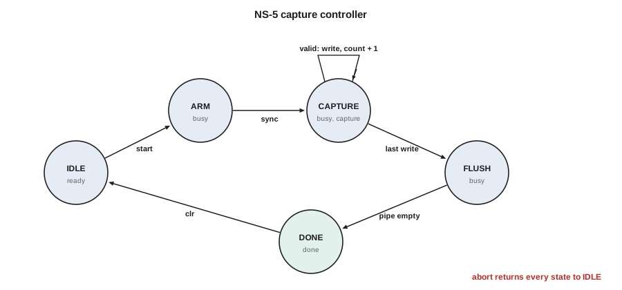
The capture controller has five states. IDLE waits for the start bit. ARM waits for the frame-sync pulse from the radar so that frames begin at a known chirp. CAPTURE counts samples as they are written. FLUSH waits for the filter's pipeline to empty, which takes 80 cycles for the last of the four channels, so that the last output is in the buffer. DONE holds the done flag until firmware clears it. A clear or abort from firmware returns the machine to IDLE from any state.
Coding styles
There are three common ways to write a state machine. The one-process style puts the state register, next-state logic and registered outputs in a single always_ff block. It is compact and automatically registers every output, but every output is delayed by a cycle relative to the state change, and Mealy outputs are impossible. The two-process style separates a small always_ff block for the state register from an always_comb block that computes both the next state and the outputs. The three-process style splits the outputs into a third block, combinational for Moore and Mealy outputs or clocked for registered ones. The two- and three-process styles are the most readable and the easiest for synthesis tools to recognize as state machines, which lets them choose encodings and check for unreachable states.
typedef enum logic [2:0] {IDLE, ARM, CAPTURE, FLUSH, DONE} state_t;
state_t state, next;

always_ff @(posedge clk or negedge rst_n)          // 1: state register
    if (!rst_n) state <= IDLE;
    else        state <= next;

always_comb begin                                  // 2: next-state logic
    next = state;                                  // default: stay
    unique case (state)
        IDLE:    if (start)                   next = ARM;
        ARM:     if (sync)                    next = CAPTURE;
        CAPTURE: if (s_valid && cnt == N - 1) next = FLUSH;
        FLUSH:   if (pipe_empty)              next = DONE;
        DONE:    if (clr)                     next = IDLE;
        default:                              next = IDLE;
    endcase
    if (abort) next = IDLE;
end

always_comb begin                                  // 3: outputs
    capture = (state == CAPTURE);                  // Moore
    busy    = (state != IDLE) && (state != DONE);  // Moore
    wr_en   = capture && s_valid;                  // Mealy: same cycle as s_valid
    last    = wr_en && (cnt == N - 1);             // Mealy
end

always_ff @(posedge clk)                           // registered flag to firmware
    done_irq <= (state == DONE);
The enumerated type makes waveforms show state names rather than numbers and lets the tool choose the encoding. The default assignment next = state keeps the next-state block free of latches, and the default branch sends any illegal code back to IDLE.
Simulating the controller
Before writing a testbench, it is worth building a quick executable model of a state machine to check the sequence and the cycle on which each output changes. The model below steps the capture controller cycle by cycle, with a frame of four samples instead of 1,024 to keep the trace short, samples arriving every other cycle and a three-cycle flush. It prints the state and outputs in each cycle.
N, FLUSH_CYCLES = 4, 3

def step(st, inp):
    """one clock cycle: returns (next state, outputs) from current state and inputs"""
    s, cnt, fl = st
    capture = s == "CAPTURE"
    wr_en = capture and inp["valid"]                 # Mealy output
    last = wr_en and cnt == N - 1                    # Mealy output
    busy = s not in ("IDLE", "DONE")                 # Moore output
    nxt, ncnt, nfl = s, cnt, fl
    if s == "IDLE" and inp["start"]:
        nxt = "ARM"
    elif s == "ARM" and inp["sync"]:
        nxt, ncnt = "CAPTURE", 0
    elif s == "CAPTURE" and wr_en:
        ncnt = cnt + 1
        if last:
            nxt, nfl = "FLUSH", 0
    elif s == "FLUSH":
        nfl = fl + 1
        if nfl == FLUSH_CYCLES:
            nxt = "DONE"
    elif s == "DONE" and inp["clr"]:
        nxt = "IDLE"
    return (nxt, ncnt, nfl), dict(busy=busy, wr_en=wr_en, last=last, done=s == "DONE")

st = ("IDLE", 0, 0)
print("cyc state    start sync valid | busy wr_en last done cnt")
for cyc in range(18):
    inp = dict(start=cyc == 1, sync=cyc == 4, valid=cyc % 2 == 1, clr=cyc == 16)
    nst, out = step(st, inp)
    b = lambda v: "1" if v else "."
    print(f"{cyc:3d} {st[0]:8s}   {b(inp['start'])}    {b(inp['sync'])}    {b(inp['valid'])}   |"
          f"   {b(out['busy'])}    {b(out['wr_en'])}     {b(out['last'])}    {b(out['done'])}  {st[1]}")
st = nstcyc state start sync valid | busy wr_en last done cnt 0 IDLE . . . | . . . . 0 1 IDLE 1 . 1 | . . . . 0 2 ARM . . . | 1 . . . 0 3 ARM . . 1 | 1 . . . 0 4 ARM . 1 . | 1 . . . 0 5 CAPTURE . . 1 | 1 1 . . 0 6 CAPTURE . . . | 1 . . . 1 7 CAPTURE . . 1 | 1 1 . . 1 8 CAPTURE . . . | 1 . . . 2 9 CAPTURE . . 1 | 1 1 . . 2 10 CAPTURE . . . | 1 . . . 3 11 CAPTURE . . 1 | 1 1 1 . 3 12 FLUSH . . . | 1 . . . 4 13 FLUSH . . 1 | 1 . . . 4 14 FLUSH . . . | 1 . . . 4 15 DONE . . 1 | . . . 1 4 16 DONE . . . | . . . 1 4 17 IDLE . . 1 | . . . . 4
The trace makes the timing explicit. Start is seen in cycle 1 and the machine is in ARM from cycle 2. Sync in cycle 4 moves it to CAPTURE in cycle 5. The Mealy output wr_en goes high in the same cycle as each valid sample, in cycles 5, 7, 9 and 11, and last marks the fourth write in cycle 11, so the counter and the buffer write happen with no delay. FLUSH occupies cycles 12 to 14, DONE begins in cycle 15, and the registered done_irq of the listing would reach firmware one cycle later. The clear in cycle 16 returns the machine to IDLE. If wr_en had been a Moore output, the controller would have needed an extra state per sample or a one-cycle-late write, and the trace would show it immediately.
State encoding
A machine with S states can be encoded in binary with ceil(log2 S) flip-flops, in one-hot code with S flip-flops and exactly one bit set, or in Gray code, where successive states in a sequence differ in one bit. FPGAs are rich in flip-flops and poor in wide logic, so one-hot encoding is usually fastest: the next-state logic for each bit depends only on the states that lead to it and a few inputs, typically fitting in one LUT, and decoding an output from the state takes no logic at all.
Worked problem
Flip-flops and unused codes for the capture controller
The controller has five states. How many flip-flops and how many unused codes does each encoding have?
Show solution
- \[ \text{binary: } \lceil \log_2 5 \rceil = 3 \text{ flip-flops}, \quad 2^3 - 5 = 3 \text{ unused codes}\]
- \[ \text{one-hot: } 5 \text{ flip-flops}, \quad 2^5 - 5 = 27 \text{ unused codes}\]
- \[ \text{Gray: } 3 \text{ flip-flops}, \quad 3 \text{ unused codes}\]
- One-hot uses two more flip-flops but its next-state equations are simpler. Its 27 illegal codes, such as two hot bits, can only arise from an upset or a reset problem.
Answer: Binary 3 flip-flops (3 unused codes), one-hot 5 (27 unused), Gray 3 (3 unused).
Unused codes raise the question of safety. If radiation, a power glitch or an asynchronous input violating setup time throws the state register into an illegal code, the machine may lock up. Synthesis tools optimize away the default branch of a case statement when they can prove that the illegal codes are unreachable in normal operation, so writing default: next = IDLE does not by itself make the machine recover. Tools provide an option, usually called safe state machine or safe recovery, that preserves the recovery logic, at a small cost in area and speed. For the NS-5, which will sit on a pole for years, Ines asks for safe encoding on the controller and for the watchdog in firmware to restart the front end if a frame does not complete.
Parameters and generate
Parameters make a module a template. A parameter declared in the module header, such as parameter int N = 1024, can be overridden at each instance, while a localparam is computed inside and cannot be changed from outside. The system function $clog2 computes the number of bits needed to count to a value, so a counter declared logic [$clog2(N)-1:0] cnt has exactly the right width for any frame size. Parameters are evaluated at elaboration, before synthesis, so they cost nothing in hardware.
Generate constructs build structure from parameters. A generate for loop replicates instances or logic; a generate if or case chooses between alternative implementations. Both are evaluated at elaboration, so the loop index, declared as a genvar, is a constant in each copy.
module chan_capture #(
    parameter int CH = 4,               // number of radar channels
    parameter int W  = 12,              // bits per sample
    parameter int N  = 1024,            // samples per frame
    parameter bit PIPE = 1              // register the outputs
) (
    input  logic                   clk,
    input  logic [CH-1:0][W-1:0]   adc,   // packed array: one sample per channel
    input  logic                   wr_en,
    output logic [CH*W-1:0]        word,  // all channels in one wide word
    output logic [$clog2(N)-1:0]   addr
);
    for (genvar c = 0; c < CH; c++) begin : g_ch
        if (PIPE) begin : g_reg
            always_ff @(posedge clk)
                if (wr_en) word[c*W +: W] <= adc[c];
        end else begin : g_wire
            assign word[c*W +: W] = adc[c];
        end
    end

    always_ff @(posedge clk)
        if (wr_en) addr <= (addr == N - 1) ? '0 : addr + 1'b1;
endmodule
The indexed part-select word[c*W +: W] selects W bits starting at bit c × W, which is the only way to slice a vector with a variable base because the width must be constant. The generate blocks are named, g_ch[0].g_reg and so on, so that the hierarchy in simulation and in timing reports is readable. Named generate blocks are a small habit that saves time whenever someone has to find a path in a report of thousands.
Hierarchy and reuse
Good designs are built from small modules with clean interfaces. The capture controller does not know how samples arrive or where they go; it sees a valid signal and drives a write enable. That separation makes each block testable on its own, as lesson 4 shows, and lets the team reuse blocks: the same parameterized capture block will serve the two-channel NS-5 Lite. Interfaces between modules should be registered where practical, because a register at every module boundary keeps timing paths inside one module and makes timing problems local, a rule lesson 9 explains in timing terms.
Common mistakes
MistakeResetting every datapath register by habit.
InsteadReset control state and valid flags; leave datapath registers unreset so they map to shift-register LUTs and hard-block registers.
MistakeReleasing an asynchronous reset asynchronously.
InsteadAssert reset asynchronously but release it synchronously through a reset synchronizer.
MistakeAssuming default: next = IDLE makes a state machine recover from illegal states.
InsteadEnable the synthesis safe-state option when recovery from upsets matters.
MistakeDriving outputs that leave a module from Mealy logic.
InsteadRegister outputs at module boundaries to keep timing paths local and outputs glitch-free.
MistakeHard-coding widths that depend on parameters.
InsteadCompute widths with $clog2 and localparam so the block scales correctly.
Summary and key terms
- always_ff blocks with non-blocking assignments describe flip-flops; enables and resets map to dedicated flip-flop inputs.
- FPGA flip-flops initialize at configuration; reset control logic, not every datapath register, and release resets synchronously.
- Moore outputs depend on state only; Mealy outputs also depend on inputs and react in the same cycle.
- Two- and three-process FSM styles separate the state register, next-state logic and outputs.
- One-hot encoding suits FPGAs; safe-state options are needed for recovery from illegal states.
- Parameters, $clog2 and generate blocks build families of circuits from one description.
- Moore machine
- A state machine whose outputs depend only on the current state.
- Mealy machine
- A state machine whose outputs depend on the current state and the current inputs.
- One-hot encoding
- A state encoding with one flip-flop per state and exactly one bit set at a time.
- Control set
- The combination of clock, enable and reset signals shared by flip-flops in a logic block.
- Synchronous deassertion
- Releasing a reset aligned to the clock so that all flip-flops leave reset in the same cycle.
- Shift-register LUT
- A LUT configured as a shift register of up to 32 stages.
- Generate block
- A construct evaluated at elaboration that replicates or selects hardware based on parameters.
- Elaboration
- The step before synthesis or simulation that resolves parameters and builds the design hierarchy.
Practice problems
Work each problem on paper first, then reveal the answer to check.
How many flip-flops does a binary-encoded machine with 12 states need, and how many for one-hot?
Show answer
ceil(log2 12) = 4 for binary; 12 for one-hot.
What width does a counter from 0 to 1,023 need, and what does $clog2(1024) return?
Show answer
10 bits; $clog2(1024) = 10.
Why might a filter delay line fail to map to shift-register LUTs?
Show answer
If its registers have a reset, or if intermediate taps are read in parallel beyond what the primitive supports.
In the trace, why does last appear in the same cycle as the fourth valid sample?
Show answer
It is a Mealy output computed from the state, valid and the count, so it needs no extra cycle.
Lesson quiz · 5 questions
Score 60% or more to complete this lesson.
Create a free account to save your progress, take quizzes and earn a certificate.